
Technology lessons for educational technology integration in the classroom. Content for teachers and students.
Elapsed time, velocity and the Micro:bit
In this lesson, we are going to use the magnetic sensor to calculate the velocity of a car moving across a track.
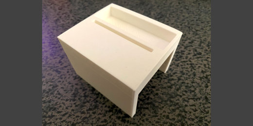
This is the setup. I have a toy car, Hot Wheels, with a magnet attached to the roof. The car is on a Hot Wheels track. Next to the car and track is a sensor gate. The sensor gate has a Micro:bit. The micro:bit will use the magnetic sensor to detect the passage of the car and magnet through the gate. A small distance away is another sensor gate. This gate is also set to detect the passage of the car and magnet.

In this lesson, we are going to use the magnetic sensor to calculate the velocity of a car moving across a track.
This is the setup. I have a toy car, Hot Wheels, with a magnet attached to the roof. The car is on a Hot Wheels track. Next to the car and track is a sensor gate. The sensor gate has a Micro:bit. The micro:bit will use the magnetic sensor to detect the passage of the car and magnet through the gate. A small distance away is another sensor gate. This gate is also set to detect the passage of the car and magnet.
The micro:bit will start a clock when the car passes through the first gate. The clock will stop when the car passes through the next gate.
Knowing the distance and time between the gates will help us calculate the velocity of the car. The micro:bit will provide the time it took the car to travel a specific distance. It will be up to us to calculate the velocity.
Disclaimer
I am not affiliated with Hot Wheels or the company that represents Hot Wheels. You don’t have to use Hot Wheels. I like to use them because they are small, inexpensive, and include tracks.
The gates
I designed the start and end gates with Tinkercad. The design is free to download and print. The links to the models and preview of each model are available in the resources section.
The first gate is designed to have enough clearance for a regular Hot Wheels car and a small magnet. The gate has a bed to hold the battery pack. The gate prints upside down so you don’t have to worry about removing supports.

The second gate is not designed to be a gate specifically. I use this to hold the micro:bit for a variety of activities. The holder is available in two formats. One format holds the regular AAA battery holder. The other format holds the lithium rechargeable battery.


The cars and tracks are available online. I found the best prices on Amazon.

The magnets are also available on Amazon. You can get the cars, track, and magnets for less than fifty dollars. You don’t have to use the 3D printed gates. Use small cardboard boxes or structures build with popsicle sticks.
I’m not providing links to the resources on Amazon because links tend to change and suppliers tend to disappear.
Code Resources
Transmit Gate code (Make Code):
https://makecode.microbit.org/_DDhaW6diba5i
Transmit Gate code (Github):
https://github.com/digitalmaestro/startgate
Receive Gate code (Make Code):
https://makecode.microbit.org/_42eAezdFw0K0
Receive Gate code (Github):
https://github.com/digitalmaestro/finishgate
3D print resources
enclosed gate
Enclosed Gate preview
Enclosed Gate download (Thingverse)
https://www.thingiverse.com/thing:4837474
Enclosed Gate download donate at Cult 3D
micro:bit holder
Micro:bit holder with lithium battery support preview:
Micro:bit holder with lithium battery support (Thingverse)
https://www.thingiverse.com/thing:4837487
Micro:bit holder with lithium battery support donate at Cults 3D
Micro:bit holder with AAA battery support preview:
Micro:bit holder with AAA battery support download at Thingverse
https://www.thingiverse.com/thing:4837494
Micro:bit holder with AAA battery support donate at Cult 3D
Magnetic direction and strength
The sensor on the micro:bit is located behind the buttons. The sensor is part of the chip dedicated to the compass. Version 1.3B has the chip near the extreme left edge.

Version 1.5 has the chip on the left edge too. It is integrated into one chip that contains both the accelerometer and compass.

Version 2.0 has the chip in the same general location. It is a little larger than the others.

The sensor readings will be stronger when the magnet is closest to the sensor. In my lesson, the car will travel from right to left. The sensor is on the right side when the micro:bit is facing this direction. The sensor will detect the magnetic field almost as soon as the car is next to the micro:bit.

The strength of the magnetic field depends on the size and type of magnet.
This part of the lesson will gather information on magnetic field strength. We will use that information to set up the conditions for starting and stopping the timer.
We need to know the approximate strength of the magnetic field when the car is closest to the starting position. We want the starting position to be close to the right edge of the Micro:bit. This will start the timer as soon as the car enters the gate.
Use the link below to access the Make Code development page.
Click the New Project tile.

Use ‘magneticStrength’ for the project name; click the Create button.

The start gate will send a signal to the finish gate when the car enters the magnetic field. We need to know what that information looks like before creating the code.
The micro:bit measures the strength of the magnetic force from three directions. The measurements are along the x, y, and z-axis.
The x-axis runs left to right along the long edge of the Micro:bit.

The y-axis runs up and down along the short edge.

The z-axis runs through the Micro:bit.

We are going to collect information from one of these directions. This information will be stored in a variable.
Go to the Variables code category; click the ‘Make a Variable’ button.

Use ‘x-axis’ for the variable name; click the OK button.

Three blocks are created for each variable. The first block is the variable itself. The Set block is used to assign values to the variable. The values can be numbers, letters, or operations. The Change code block is used to change variables with numbers with some regular amount.

Get the [set x-axis] code; place it in the [forever] loop.
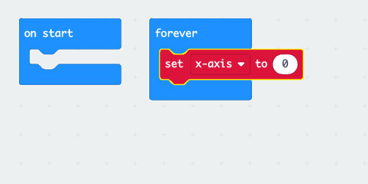
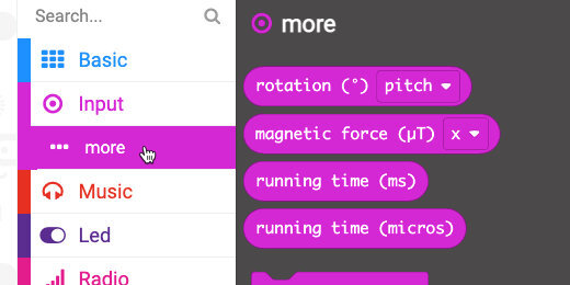
Select the Input category and then the more option. Look for the [magnetic force] code block.
Place the code block into the set variable parameter. The block is already set to get values from the x-axis.

The value in the variable will continuously update. We won’t display the information on the micro:bit display. This would take too long to get the information we need.
We are going to send the information directly to the computer, which can display information faster. The information is sent along the cable. The cable is a Universal Serial Bus, USB. There is a code block that sends information along the Serial cable.
Click the Advanced code category button.

Select the Serial code category.
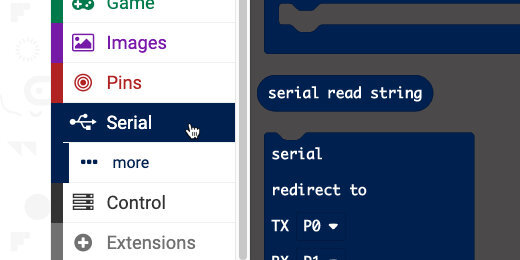
Find the [Serial write value] code block.

Place the code block in the [forever] loop; after the set variable code.

Type x-axis into the value label field.

Go to the Variables category. Get the [x-axis] variable; place it into the value field.

This is all the code we need to collect the magnetic field strength along the x-axis.
Connect your micro:bit to the computer. Click the Action menu and select ‘Download to micro:bit’.

Leave the micro:bit connected to the computer.
A ‘Show console Device’ button appears in the simulator area. Click the button to open the console.

The bottom of the console displays the stream of magnetic field values detected by the sensor.

A scrolling chart plots the values as they increase or decrease.

Get a small magnet and move it along the bottom of the Micro:bit. The numbers will go up and down.
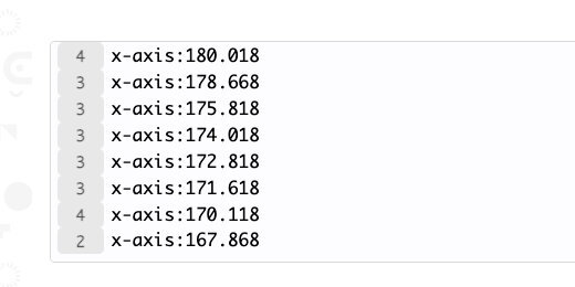
Sometimes the values will change from positive to negative.

Magnetic field strength
We are not interested in the value from one axis. We want to get the overall magnetic field strength from the magnet. This will assure that we won’t miss the start and finish as the car passes through the magnetic field.
Click the ‘Go back’ button.

Click the force axis selector; choose strength.
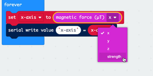
Change the value label to ‘strength’.

Click the variable selector; select ‘Rename variable’.

Use ‘strength’ for the variable name.

Download the updated code to the Micro:bit; click the ‘Show console Device’ button.
Move the magnet around the micro:bit to find the point where the magnetic force is strongest. It should be strongest along the right bottom edge.

The strength is over 1,000 when the magnet is near.

Move the magnet about an inch away.

The strength value drops by over a thousand with my magnet.

We only need to look for a moderate increase in the magnetic strength.
There are times when the measurements appear as negative values. We will fix this in our code later.
Click the ‘Go back’ button. Click the Home button to return to the Make Code main page.

Start gate
The start gate has the simplest task. It will sense the magnetic field strength from the magnet. When the detected magnetic field is at a specific strength it will trigger a message. The message is sent to the second gate. The second gate micro:bit takes care of starting and stopping the timer. It will also display the elapsed time.
Click the ‘New project’ tile.

Use ‘startGate’ for the project name.

This micro:bit will send a signal to the finish gate. We need to activate the Radio function. The Radio function is used by one micro:bit to send information to another.
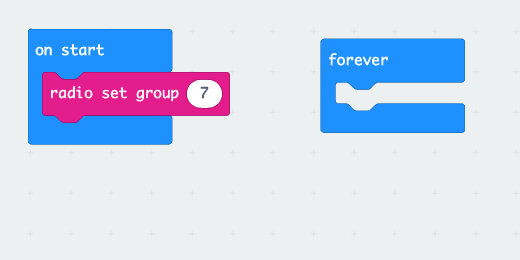
Select the Radio code category; find the [radio set group] code.

Place the code into the [on start] section.

The radio group is a number. This number is like a channel. There are 256 possible channels, 0-255. We can use any channel. All the Micro:bits that need to communicate with one another must be using the same channel. Set the radio group to channel 7, just for practice.
The micro:bit needs to decide when to send the message. Decisions are made using deductive logic. This logic is in the form of, ‘If something is True Then perform some action’.
There is more information on if-then statements on the CK-12 website. https://bit.ly/3nzyGJy
Go to the Logic category; look for the [If True Then] code block.

Place the code into the [forever] loop.

The True parameter in the logic condition is another logic operation. This is where we look for a value or a comparison.
Go back to the Logic category; find the Equal comparison code.

Place the comparison code into the True parameter.

Go to the Input codes and get the [magnetic force] code.

Place the code on the left side of the comparison code.

Change the force input from the x-axis to strength.

Use the comparison selector to select ‘greater than or equal to’.

We know that the magnetic strength can reach a strength of over 1,000. We also know that the strength can go down to less than 100. A value in the middle of this range would be a good way to determine the presence of the car and magnet. Enter 500 into the right side of the comparison.

If the magnetic strength is equal to or greater than 500, we want to send a signal to the other Micro:bit.
Go to the Radio codes; find the [radio send string] code.

Place the code inside the condition.

Type ‘team1’ into the string assignment.

I am using a keyword for the string. This keyword serves an important purpose. It provides a codeword that verifies the authentication of one micro:bit to the other.
This verification is important in the classroom. Students often forget to set the radio channel to anything other than channel 1. It is also possible that students or groups might select the same group number. Even if multiple Micro:bits are using the same radio channel, the keyword provides a verification before a message is accepted.
Go to the Basic code category. Find the [show icon] code block.

Place the icon code after the radio send code.

Click the icon selector and choose the Happy icon. This provides feedback so we know the magnetic strength was detected and exceeded the 500 microteslas we selected.

Return to the Basic codes and find the [pause] code block.
Place the code block after the icon code.

Click the time selector; choose 500 milliseconds.

Get the [clear screen] code block from the basic section; place it after the pause code.

We need the pause and clear code to erase the icon after displaying the confirmation. It clears the display for future trials.
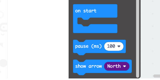
We should identify this micro:bit as the start gate. Get the [show string] code from the Basic code category. Place the code into the [on start] section.

Replace the hello string with the letter ’S’.

Connect the micro:bit to the computer. Click the action menu and select Download to micro:bit.

Eject the micro:bit and set it to one side. Let’s get to work on the code for the other Micro:bit.
Finish Gate
Click the Home button to return to the Make Code micro:bit home page.

Click the New Project tile. Use ‘finishGate’ for the project name.

Get the [radio set group] code from the Radio category. Place the code into the [on start] section. Change the radio channel from 1 to 7.

This micro:bit listens for a message sent from the start gate micro:bit. Go to the Radio codes; look for the [on radio received ‘receivedString’] code block.

Place the code block on the canvas.

When the micro:bit receives a string, we need to verify the string. This is another example where we need a condition to check for something to be True.
Get the [if True then] code block; place it into the [on radio received] code.

Go back to the Logic codes; find the string comparison code. This code has quotes inside each side of the comparison parameters.

Place the code into the condition parameter.

Type ‘team1’ into the right side of the comparison.
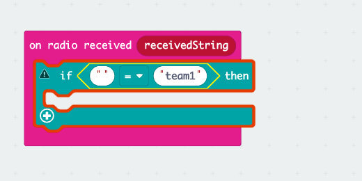
The ‘receivedString’ block on the [on radio received] code is a code block variable. It holds received signals from micro:bit devices.
Drag the code block from the [on radio received] parameter; place it into the left side of the comparison code.

The code verifies that the string received matches the string we need to start the timer.

When the string is received, we need to capture the current elapsed time on the micro:bit. The elapsed time is measured in milliseconds. There are one-thousand milliseconds in one second. The time will be saved to a variable.
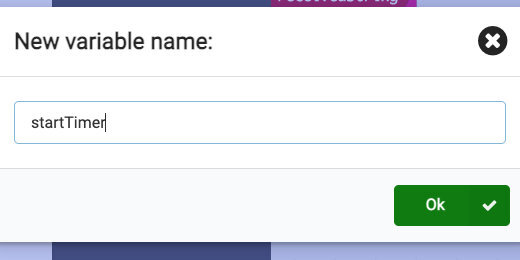
Go to the Variables category; click the ‘Make a Variable’ button.

Use ‘startTimer’ for the variable name.
Get the [set ‘startTimer’ to] code; place it into the condition statement.

Go to the more code section of the Input codes; find the [running time (ms)] code block.

Place the code into the value assignment parameter of the [set ‘startTimer’ to] code.
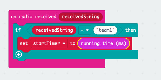
The current running time is stored in the [startTimer] variable. We need feedback to know this has been done. Go to the Basic codes; get the icon code block. Place the code after the set variable code. Leave the icon set to the heart.

This code gets the running time value from the micro:bit the moment it receives the message.
Review of what is happening
This is how it works. Let’s assume the start micro:bit sends the signal and it is received by the finish gate micro:bit. Let’s assume that the finish gate micro:bit has been running for 8000 milliseconds, 8-seconds. This value is stored in the variable ‘startTimer’. The car activates the sensor on the finish gate after 11000 milliseconds, 11-seconds.
We subtract the second reading, 11 seconds, from the first, 8 seconds. This gives the total elapsed time since the timer was triggered by the start gate.
Finish time
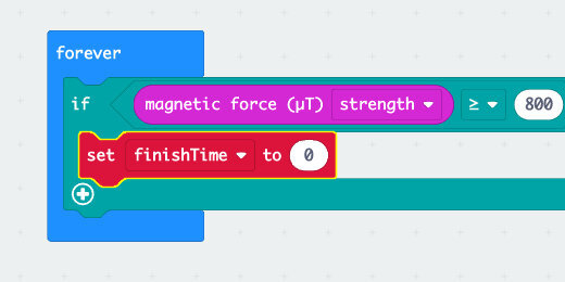
To get the finish time, we will create some code that is similar to the one from the first gate. The code will be in the [forever] loop so it is always looking for a change in the magnetic field strength.
Go to the Logic codes and get the [if True then] code block. Place the code into the [forever] loop.

Get the comparison code; place it into the True condition parameter.

Change the comparator to greater than or equal to.

Get the [magnetic force] code from the Input codes; place the code into the left side of the comparator.

Change the force vector to measure the strength of the magnetic field.

Enter the magnetic field strength you want to sense into the comparator. This can be the same value we used for the start gate.

We want to record the current running time when the car is close to the gate. This information will be stored in another variable.
Go to the Variables category; click the ‘Make a Variable’ button. Set the name of the variable to ‘finishTime’. Place the [set ‘finishTime’ to] code into the condition statement.
Get the [running time (ms)] code from the Input category. The code is under the More codes option. Place the code into the value assignment for the ‘finishTime’ variable.

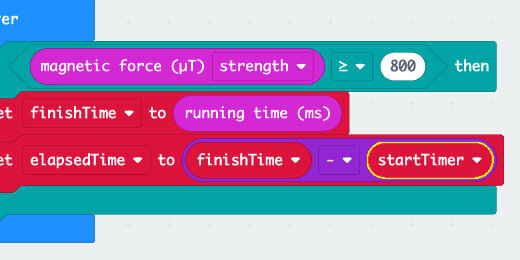
We have the first running time saved in one variable and the second time saved in another. We can now subtract these values to get the time it took to travel from the first gate to the second.
We need another variable to store the results. Go to the Variables category. Create a new variable; use ‘elapsedTime’ for the variable name. Place the [set ‘elapsedTime’ to] code after the other set variable code.

Go to the Math code category; find the subtraction operation.

Place the operation into the assignment parameter for the [set ‘elapsedTime’ to] code.

Get the ‘finishTime’ variable; place it into the left side of the subtraction operation. Get the ‘startTime’ variable; place it on the right side of the operation.
convert seconds
The difference is calculated and represented in milliseconds. We can keep the answer in milliseconds, but I think it is much better to get the result in seconds. To convert milliseconds to seconds we need to divide by 1000.
We need another variable to store the answer. Go to the Variables category. Create a new variable; use ‘seconds’ for the variable name. Place the [set ‘seconds’ to] code after the [set ‘elapsedTime’ to] code.

Go to the Math codes; get the division operation. Place the operation into the assignment parameter for [set ‘seconds’ to].
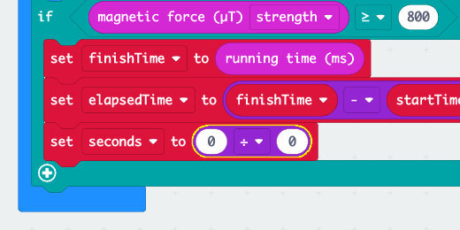
Get the [elapsedTime] variable; place it into the left side of the division operation. Enter 1000 into the right side of the operation.

A confirmation
We need a way of knowing that the magnet’s passage recorded and the micro:bit calculated the elapsed time. Get the [show icon] code; place the code after the last code in the condition statement. Change the icon to a checkmark.

The elapsed time
Go to the Input category; find the [on button A pressed] code.

Place the code on the workspace.

Get the [show number] code from the Basic code category; place it into the [on button A pressed] function. Get the [seconds] variable; place it into the show number parameter.

Identify the micro:bit
We need to identify this micro:bit as the finish gate. Place the [show string] code, from the Basic section, into the [on start] section. Use the letter ‘F’ for the string value.

Absolute field strength
We need to take care of one more item. During our magnetic field strength at the beginning of the lesson, we noted that the values sometimes flipped from positive to negative. We need to take care of that to avoid false readings.
This is what could and does happen, at least during my trials. A magnetic value of (-900), negative 900, will not trigger the code to start or stop the timer. This happens because negative 900 is not greater than or equal to positive 500.
Go to the Math code category; find the [absolute of] code.

Place the code above and to the right of the [forever] loop, not in the loop.

Get the [magnetic force] code and place it into the [absolute of] parameter.

Get the code blocks and place them back into the left side of the comparator.

Click the action button and download the code to the micro:bit. Eject the micro:bit. Click the Home button.

Open the ‘startGate’ project. Connect the start gate micro:bit.

Get the [absolute of] code block; place the [magnetic force] code into the parameter. Place both blocks back into the comparator. Download the code into the micro:bit.

Off to the races!
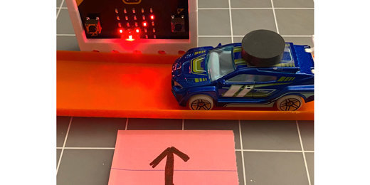
The image below shows the car on the track. The car and track are against the gate to get the best signal strength possible.

The happy icon appears when the magnetic force is greater than or equal to 500.

The finish gate shows it is waiting for the timer signal.

The heart icon shows the timer message was received.

Once the car enters the gate, a checkmark icon appears to indicate the magnet was sensed and the elapsed time was calculated.

Press button A to display the elapsed time.

Calculating velocity
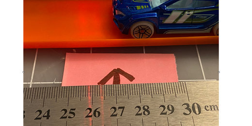
To calculate the velocity we need one more piece of information. We need to know the distance between the gates. It helps if we can get a good measure of the distance. We need to know the point where the start and finish gates record the running time.
Place the finish gate next to the track where it will record the finish. Move the car slowly up to the gate. Stop when the checkmark appears. Place a mark to show the point where the front of the car marks the finish line. Repeat the process with the start gate.
Get a ruler and measure the distance between the two marks.
Final notes
Be careful not to bring a magnet close to the finish gate after it has recorded the elapsed time. This will cause it to update the elapsed time with new values.
Micro:bit timer and stopwatch
This lesson will use the internal timer to create a basic stopwatch program. The program in this lesson is based on the code provided by Micro:bit to learn the fundamentals. I’ve taken it and expanded on the explanations.

Timer and stopwatch
Every computer and microcontroller has a built-in clock. This clock is important because it is used to synchronize operations and data transmission. Computers have a built-in rechargeable battery that keeps a clock going when the computer is not powered. This clock is used to keep track of the date and regular time according you your timezone.
Each computer also has an internal timer that begins when the computer starts. The Micro:bit has an internal timer that begins when it is powered or restarted. The timer keeps track of events and coordinates the synchronization of operations and data transfer.
This lesson will use the internal timer to create a basic stopwatch program. The program in this lesson is based on the code provided by Micro:bit to learn the fundamentals. I’ve taken it and expanded on the explanations. The link to the Make Code micro:bit lesson is available below.
https://makecode.microbit.org/projects/stopwatch
Project previews
Use the links below to get a preview of the final project.
StopWatch Make Code:
https://makecode.microbit.org/_PuY8zVbzuXDd
StopWatch Github:
https://github.com/digitalmaestro/stopwatch
Stopwatch
Use the link below to access the Micro:bit development environment. You don’t need an account to begin creating projects for Micro:bit.
Click the Create new project button.

Use “stopWatch” for the project name; click the Create button.

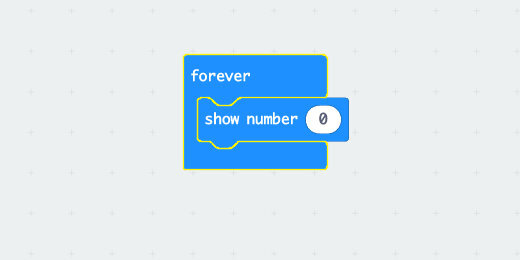
Every new project includes two code blocks on the coding workspace. These blocks include the [on start] section and [forever] loop.

The [on start] section is used to run code as soon as the Micro:bit starts or is restarted. This is where we usually define variables. We will use plenty of variables in our project.
The [forever] loop runs code for as long as the Micro:bit is powered. Code inside this loop does not require any user interaction. We won’t be using the [forever] loop in this project.
Get the [forever] code block and drag it to the Codes Section. Release the code block when a Trash Can icon appears.

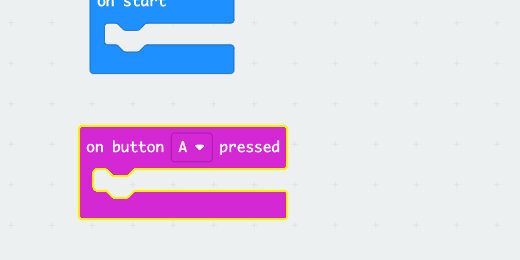
Go to the input section; find the [on button A pressed] code block.

Place a copy of the code block on the workspace.
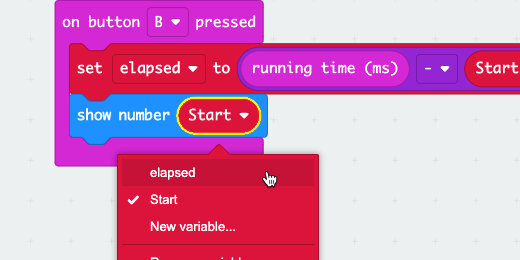
The internal timer begins the moment the Micro:bit starts. There is no way to reset the timer once the Micro:bit has started. We need to capture a moment from the internal timer and save it for use later. That moment will be saved in a variable.
Go to the Variables section; click the ‘Make a Variable’ button.

Use ‘Start’ for the variable name; click the OK button.

Three blocks are created for each variable. The first block is the variable itself. The Set block is used to assign values to the variable. The values can be numbers, letters, or operations. The Change code block is used to change variables with numbers with some regular amount.

Place the [set Start to] code block into the [on button A pressed] function.

Select the Input code category and click the more option.
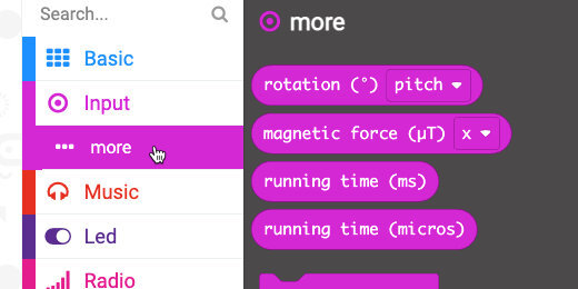
There are two runtime code options. One records time in milliseconds(ms), and the other in microseconds(micros). There are one-thousand milliseconds in one second. There are one million microseconds in one second.
We are going to use the millisecond option.

Place the [running time (ms)] code into the set variable parameter.

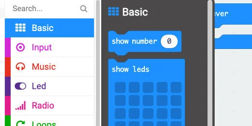
Let’s get an idea of what this timestamp in the [Start] variable looks like. Go to the Basic code category; find the [show number] code block.

Place the code block into the [on button A pressed] function and below the set variable code.

Go to the Variables section; get the [Start] code. Place the code into the [show number] parameter.

Go over to the simulator and click on button A.

A number will scroll across the display. This is the elapsed time since the virtual Micro:bit started.

Click button A again; the number will be larger because more time has elapsed.

The variable has captured this moment in time from the Micro:bit. With this time saved, we will subtract a future time to give us the elapsed time.
We need another variable to save the elapsed time. Go to the Variables section; click the ‘Make a Variable’ button. Use ‘elapsed’ for the variable name.

The elapsed time will be calculated and saved when we press another button. Go to the Input section. Get the [on button A pressed] code block. Place it onto the workspace.
The second [on button A pressed] code block is green with hash marks. The code is inactive because we cannot have two code blocks that refer to the same button at once.

Click the button selector; choose button B.

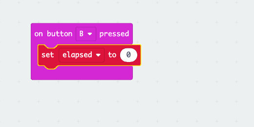
Go to the Variables category; get the set elapsed code block. Place the code block into the [on button B pressed] function.
We need to subtract the current run time from the one recorded and saved in the Start variable. Go to the Math code category; find the Subtraction operation.

Place the code block into the Set Variable parameter for the button B function.

Go to the Input category and the more section. Get the [running time (ms)] code block. Place it into the left side of the subtraction operation.

Go to the Variables section. Get the [Start] variable; place it into the right side of the subtraction operation.

Go to the [on button A pressed] function. Right-click on the [show number] code block; select the duplicate option.
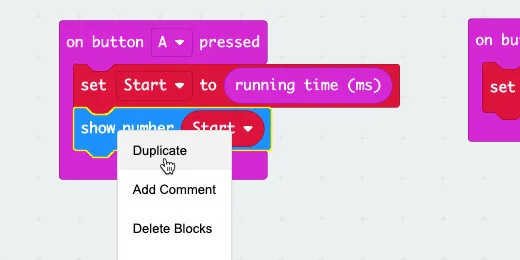
Get the duplicate code and place it into the [on button B pressed] code; place it after the set variable code.

Click the variable selector; choose the [elapsed] variable.
Elapsed time in milliseconds
Click button A in the simulator. A long string of numbers will scroll across the display. This is the time in milliseconds. Reading the time in milliseconds is not human-friendly. Let's get the Micro:bit to display the times in seconds.
Elapsed time in seconds
One-thousand milliseconds is one second. We need to divide the total milliseconds by 1000.
Go to the Math code category. Get a copy of the Division operation and place it on the workspace below the [on button A pressed] function. Don’t put it into the function yet.

Get the [Start] variable from the [show number] code; place it into the left side of the division operation.

Place the division operation into the [show number] code parameter.

Type 1000 into the right side of the division operation.

Repeat the process for the button B code.

Click button A in the simulator. Wait a second or two and click button B. The values scrolling across the display will begin with a whole number followed by a number rounded to two decimal places.
Press button A to get the latest running time. Press button B to get the updated running time and subtract it from the first. This is your basic stopwatch.
If you press button B again—without pressing button A first—you will see a longer elapsed time. This is like a stopwatch lapse function.
Click the Actions menu and select Download to Micro:bit.

Micro:bit conductivity tester
The conductivity tester in our lesson will help us identify items that are conductors, resistors, or insulators. Conductors and resistors are very similar. Both of them allow electrons to flow through a circuit. Resistors allow less of the electrons to flow. Some electronic components need more current and some require less. Too much current going to a component that requires less can damage the component. Resistors are used to reduce the amount of current going into those components.

Conductivity tester
There are items everywhere that conduct electricity. They allow electrons to flow from one end of a circuit to another. Some items are better at conducting electricity than others. Items that resist the flow of electricity are called resistors. Some items prevent the flow of electronics completely. These are known as insulators.
Conductors and resistors are very similar. Both of them allow electrons to flow through a circuit. Resistors allow less of the electrons to flow. Some electronic components need more current and some require less. Too much current going to a component that requires less can damage the component. Resistors are used to reduce the amount of current going into those components.
The conductivity tester in our lesson will help us identify items that are conductors, resistors, or insulators.
I have created a table with items to test for conductivity and resistance. The table contains items that are solids and others that are liquids. I tried to keep the list to items that are inexpensive and easy to gather. Feel free to modify the table of items to suit the needs of your classroom.
I included items with liquids to demonstrate that not all conductors are solids. This is one reason we don’t touch circuits with wet hands. Liquids with impurities facilitate the flow of electrons.
Use this lesson for a basic introduction to conductors, resistors, and insulators. The tables include spaces for values. You might want to graph these values in your activities.
Supplies
1 Micro:bit
1 Micro:bit power supply (battery pack or computer)
2 alligator clip connectors
2 medium or large paper clips
materials to test
Resources
Use the links below to get a copy of the final project.
Basic conductivity worksheets
Extended conductivity activity
conductivity tester Make Code :
https://makecode.microbit.org/_9gDPbzK8p2Xg
conductivity tester Github :
https://github.com/digitalmaestro/conductivitytester
Conductivity tester
We are using the Make Code development environment from Microsoft. We don’t need an account to create projects with Make Code. Use the link below to access the Make Code development environment.
Click the New Project button.

Use ‘conductivityTester’ for the project name; click the Create button.

Every new project includes two code blocks on the coding workspace. These blocks include the [on start] section and [forever] loop.

The [on start] section is used to run code as soon as the Micro:bit starts or is restarted. This is where we usually define variables.
The [forever] loop runs code for as long as the Micro:bit is powered. Code inside this loop does not require any user interaction. This is where we will develop the code for our tester.
The Make Code development environment has a Micro:bit simulator. The simulator has contacts along the bottom, just like the real Micro:bit. Some of the contacts have labels. Contacts with labels 0, 1, and 2 are used for external components. The contact labeled 3V provides 3-volts to external components. The GND contact is called the Ground. All circuits need to be connected to a ground to complete the circuit. Think of the ground as the negative side of a battery terminal.
Important: Never connect the 3v and GND directly. This could severely damage your Micro:bit.
The contacts labeled 0, 1, and 2 are referred to as General Purpose Input and Output pins. They can function as either input or output. We will use one as an input.
We are going to use the simulator to provide a foundation for the readings from the actual Micro:bit. This will help us understand the information to be displayed later.

Go to the Basic code section; find the [show number] code block.
Place the code block into the [forever] loop.
Select the Advanced section to display more code block options.

Select the Pins section.

Find the [analog read pin] code block.

Place the code block into the [show number] parameter.
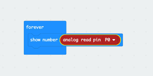
This code displays the information read by one of the contacts. The contact in this example is contact zero.
The simulator has a small number—zero—to the right of contact. This number provides feedback on simulated input. This number does not appear on the real Micro:bit. It is here to simulate input for the contact. The Micro:bit displays the number zero too.

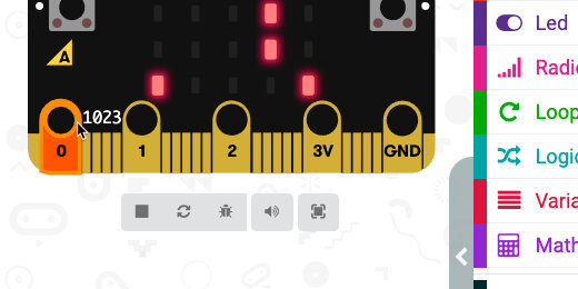
Click on the contact and drag it up. You're going to see a color bar rise as we move the mouse pointer up. The value next to the contact will increase too. This number represents electric current. The current is combing from the Micro:bit voltage supply.
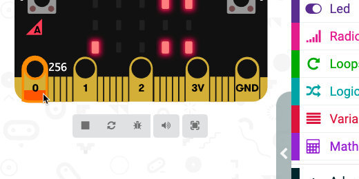
Drag the meter to the top of the contact. Stick to the edges of the contact to go around the circle or whole in the Micro:bit. The maximum value for the input is 1023.
What does the number mean?
The value of 1023 comes from Micro:bit's use of the 10-digit binary system. Every bit of information in a computer is either 1 or 0. Bits are combined to create everything in the computer. Characters are often stored in 8 or 10-bit binary strings. A string of 8 bits can represent 256 values. That number is 2 raised to the power of 8. A string of 10 bits can represent 1024 values. Increasing the number of bits provides more values and greater precision.
The Math is Fun website provides a nice explanation of the binary system. Use the link below to access the binary page for more information.
https://www.mathsisfun.com/binary-number-system.html
Variables
We need a variable to store the information read by the input pin. Go to the Variables section; click the ‘Make a Variable’ button.

Use ‘current’ for the variable name; click the OK button.

Three blocks are created for each variable. The first block is the variable itself. The Set block is used to assign values to the variable. The values can be numbers, letters, or operations. The Change code block is used to change variables with numbers using some regular amount.

Get the [set current to] code block; Place it into the [forever] loop. Place it above the [show number] code block.

Get the [analog read pin] from the [show number] parameter; place it into the [set current to] parameter. This code assigns the value read from Pin0 to the variable [current].

We don’t need the [show number] code. Right-click on the code block; select the Delete block option.

If an object is conductive, it will permit a flow of current. Any amount of current will be good enough for us to determine if an item is a conductor. The lowest value recorded by the micro:bit is zero. When it displays zero, no current is flowing through the Micro:bit. When a value is greater than zero means that some current is flowing. We will see later that this is not so for the physical Micro:bit.
Go to the Logic section; find the [if…then…else] condition code block.

Place the condition code block in the loop, after the variable.

The condition statement needs to evaluate a condition. It needs to evaluate if something is True. Go back to the Logic section; find the less-than comparison code block.

Place the Comparison code block into the condition evaluation parameter.

Click the comparison selector; choose greater-than.

Go to the Variables section. Get the [current] variable; place it on the left side of the comparison code.

If the value in the variable [current] is greater than zero then we want to display something.
Go to the Basic section; find the [show icon] code block.
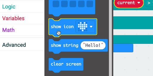
Place the code block into the first section of the condition statement.

Click the icon selector; choose the checkmark icon or any icon you prefer.

Go back to the Basic code section. Get another [show icon] code block; place it in the Else section. Change the icon to an ‘X’ or any icon you prefer.

The Micro:bit will display an X as long as the probes are not connected to an object that conducts electric current. A checkmark will appear once the probes come into contact with something that conducts electricity.
Simulation vs reality
The simulator shows that the Micro:bit returns a value of zero when it is not connected to a conductive object. This is not so for the physical Micro:bit. This is not what I expected when I downloaded the program to the Micro:bit.
When coding we often run up against things we didn’t expect. Dealing with those unexpected situations is a big part of coding. We need to calibrate the values in our code before using it to test for conductivity.
If you were watching NASA and Ingenuity, you know that unexpected things happen. The NASA programmers had to upload a fix to the program before Ingenuity could fly.
Go to the Basic code section.
Get the [show number] code block; place it after the set code.
Place the [current] variable into the [show number] parameter.
Place a Pause code block after the [show number] code.
Change the pause duration to 500(ms).
Add a [clear screen] code block after the pause code.

Click the Actions menu and select Download to micro:bit.

Don’t touch any of the contacts on the Micro:bit. The Micro:bit will display the checkmark followed by a number value. This is the pin reading from the Micro:bit. The number displayed on my Micro:bit is 208. The number displayed on yours might be different.
I went through the same process on three other Micro:bit. Each one gave me a slightly different number. The number displayed is the value at which nothing is connected to any of the contacts.
Calculate voltage
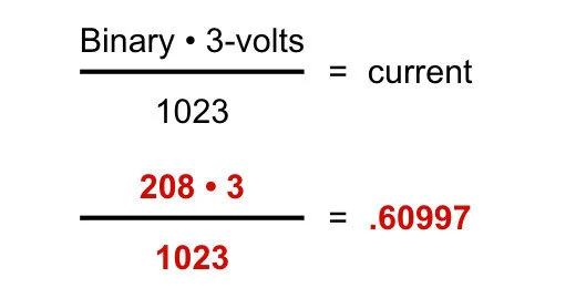
This value represents the current or volts registered by the Micro:bit. We can determine the voltage with a simple math formula. The formula is in the image below.
The total value we can get from the reading is 1023. The voltage from the Micro:bit is 3-volts. Multiply the reading from the Micro:bit, 208 in my example, by 3-volts. Divide the product by 1023. The answer for my example is .60997 volts. This is less than one volt.
We can come to an agreement that any reading that is less than 1-volt can be ignored. This eliminates the strange readings which are probably caused by static electricity and electronic devices surrounding the Micro:bit.
The binary number 1023 represents a total of 3-volts. Dividing 1023 by 3 will give us the binary equivalent of 1-volt. Return to the code; enter 341 into the comparison parameter.

Download the updated program to the Micro:bit. The Micro:bit will display the binary value from the contact reading. Use this value to calculate the voltage going through the conductor.
Connections and examples
Connect the alligator clips to the 3-volt and Pin-0 connectors.

Connect the Micro:bit to a power supply.

Don't dip the alligator clip into liquids. Don't pierce the fruit and vegetables with the clip either. Use a probe; I like paper clips.
*Don’t drink the liquids after testing!*
*Don’t eat the fruit after testing!*

Use the curled inside of the paperclip to grip the sides of containers. Glass and plastic are good insulators. Use glass or plastic to hold the liquids for testing.

Collect data from multiple micro-bits
This lesson focuses on using several Micro:bits to collect sensor information and relay that information to one Micro:bit. The one Micro:bit is connected to a computer to collect data and save it to a Comma Separated Value, CSV, file.

Sensor data from multiple micro-bits
Many classroom teachers might have one Micro:bit per student or one per group. This arrangement is nice for most applications. There are applications where we need more than one Micro:bit. For example, when we need to collect remote sensor information and send that information to a Micro:bit connected to a computer.
In another example, we need to collect remote information from several Micro:bit devices. Each device needs to pair with a separate Micro:bit to collect the data.
This lesson focuses on using several Micro:bits to collect sensor information and relay that information to one Micro:bit. The one Micro:bit is connected to a computer to collect data and save it to a Comma Separated Value, CSV, file.
Project previews
Use the links below to get a preview of the final project.
Sensor Data transmitter (Make Code): https://makecode.microbit.org/_3EzC8P6DoFch
Sensor Data transmitter (Github): https://github.com/digitalmaestro/datatransmitter
Sensor data collector (Make Code): https://makecode.microbit.org/_bLW8Kf91PcTe
Sensor data collector (Github):
https://github.com/digitalmaestro/datareceiver
The project
Use the link below to access the Micro:bit development environment. You don’t need an account to begin creating projects for Micro:bit.
Click the Create new project button.

Use “dataTransmitter” for the project name; click the Create button.

Every new project includes two code blocks on the coding workspace. These blocks include the [on start] section and [forever] loop.

The [on start] section is used to run code as soon as the Micro:bit starts or is restarted. This is where we usually define variables. We will use plenty of variables in our project.
The [forever] loop runs code for as long as the Micro:bit is powered. Code inside this loop does not require any user interaction. We won’t be using the [forever] loop in this project.
Get the [forever] code block and drag it to the Codes Section. Release the code block when a Trash Can icon appears.

The data from this Micro:bit will be sent to another Micro:bit. That Micro:bit will collect and store the information sent to it by each data transmitting Micro:bit.
Radio activation
To send data from one Micro:bit to another, we need to activate the Radio. Go to the Radio codes section. Find the [radio set group] code block.

Place the [radio set group] code block into the [on start] section.

The Radio Group code block uses a number to represent the channel for transmitting and receiving information. This channel links two or more Micro:bit devices. Micro:bits that need to communicate with one another need to be using the same group number or channel. We can use any channel from 0 to 255. That’s a total of 256 channels.
The group is set to channel 1 automatically. This channel is fine to use unless you get interference from other classroom Micro:bits. Make sure to use the same group number for the sending and receiving Micro:bit.
Go to the Input codes section. Find the [on button A pressed] code block.

Place the code block on the workspace.

When the button A is pressed the Micro:bit will send sensor information to a listening Micro:bit.
Go to the Variables section; click the Make a variable button.

Use “temperatureData” for the variable name; click the OK button.

Three blocks are created for each variable. The first block is the variable itself. The Set block is used to assign values to the variable. The values can be numbers, letters, or operations. The Change code block is used to change variables with numbers with some regular amount.

Get the [set temperatureData to] code block; place it into the button A pressed function.

Go to the Input codes section; find the [temperature] code block.

Place the code block into the set variable parameter.

The value from the temperature sensor is now stored in the [temperatureData] variable.
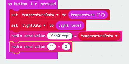
Go to the Radio code section; find the [radio send value] code block.

Place the code block into the button A pressed function. Place the code block after the value assignment.

The send value code block has two parameters. This is known as a Name-value pair. The first parameter is a label for the value in the second parameter. The label is usually something like the word temperature to identify the sent value as the temperature. When collecting data from multiple Micro:bits it is useful to know where the information came from.
Labels in the name-value pair are limited to 8 characters. I use the student or group name along with the data label. For example, 'Alextmp' or 'Grp01tmp'. I use this information to group and sort the data in a spreadsheet later.
Type ‘Grp01tmp’ into the label parameter.

Go to the variables section; get the [temperatureData] variable and place it into the second parameter.

This is the basic code needed to transmit sensor data from one Micro:bit to another. The code sends one piece of sensor information. Let’s add more sensor information to send. We’ll add the light sensor data to our set of data sent to the Micro:bit.
Go to the Variables section; click the Make a variable button. Use “lightData” for the variable name.

Get the [set lightData to] code; place it in the button A pressed function. Place it before the radio \\[send] value code block.

Go to the Input section; find the [light level] code block.

Place the [light level] code into the [set lightData to] parameter.

Get a [radio send value] code block from the Radio section. Place the code block at the end of the code blocks in the button A pressed function.
Set the label to ‘Grp01lgt’.

Get the [lightData] variable; place it into the second parameter.

Repeat this process with other sensor values you want to send.
Download to the transmitter
Connect your Micro:bit to the computer. Click the action menu button. Download this program to the sending Micro:bit. Eject and disconnect the Micro:bit.

You can download this code onto different Micro:bits using one computer. All you need to do is change the group name.
Receiving Micro:bit
Click the Home button to return to the main Make Code page for the Micro:bit.

Create a new project. Use ‘dataReceiver’ for the project name.
Get the [radio set group] code block; place it into the [on start] section. Make sure the group number is set to the same number used in the transmitting Micro:bit.

Go to the Radio code section; find the [on radio received] code block.

Place the code block on the workspace.

Click the Advanced section button.

Select the Serial code section; find the [serial write value] code block.

Place the [serial write value] code block into the [on radio received] code.
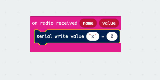
The [serial write value] code has two parameters. These parameters are like the ones we used in the radio send code. The left parameter is for the label and the right is for the value. The values for these parameters are stored in the radio received code.
Click the ‘name’ parameter and drag it down into the label parameter.

Drag a copy of the ‘value’ variable into the right parameter of the serial write value code.
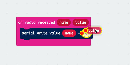
This is all the code needed for the receiving Micro:bit. Download the code to the Micro:bit. Leave this Micro:bit connected to the computer. Don’t leave the Make Code development environment. It needs to be open to collect the data and prepare it in a CSV file.
Collecting data
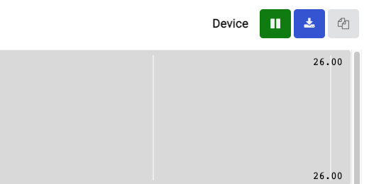
Press the button on one of the data collection Micro:bits. This activates the data collection mode on the Micro:bit and the development environment. The Micro:bit and the Make Code IDE is accepting data when you see the Show Console Device button. Click the button to enter the data display and collection portal.

Proceed to collect data from the Micro:bits once you are in the console. The values are displayed in the section at the bottom of the console. This Micro:bit has collected sensor data from three Micro:bit devices.

The collected data can be downloaded using the download button.
Micro:bit multiple sensor information
This lesson will create a program to collect data from at least three sensors on the Micro:bit. The lesson will cover a fourth sensor option for collecting moisture information. The Micro:bit has several sensors that are useful in scientific explorations. They are useful for students that want to create a science project that uses several sensors. The Micro:bit can collect data from all the sensors at the same time. This includes sensors on the Micro:bit and sensors connected to it.

Multiple sensor information
The Micro:bit has several sensors that are useful in scientific explorations. They are useful for students that want to create a science project that uses several sensors. The Micro:bit can collect data from all the sensors at the same time. This includes sensors on the Micro:bit and sensors connected to it.
Collecting and storing sensor data is useful for analyzing information over time. The Micro:bit can save the information collected from the sensors to a Comma Separated Value, CSV, file. Open the CSV file with any spreadsheet program to analyze the data and create charts.
This lesson will create a program to collect data from at least three sensors on the Micro:bit. The lesson will cover a fourth sensor option for collecting moisture information.
Here is a science exploration scenario. We have at four plants. Each plant is located in one of the four cartesian coordinates of North, South, East, and West. The purpose of the exploration is to understand how the plant’s exposure to the sun affects its growth. Each plant is cared for by a group of students. They are charged with collecting sensor information three times during the day.
The students will collect information from the light, temperature, and compass. The data will be shared with other students in the class.
A fourth sensor reading is not from one that is part of the Micro:bit. This fourth sensor reading measures the moisture content of the plant. The Micro:bit measures the amount of resistance present in plant soil. Water interacts with the soil to create a medium that conducts electricity. The more water there is in the plant the easier it is for electric current to travel from one electrode to another. One electrode is connected to a pin on the Micro:bit. Another probe is connected to the 3-volt connector. The Micro:bit measures the current flowing from one probe to another. This is similar to an experiment you might have tried where the Micro:bit is used as a conductivity tester.
The Micro:bit is connected to a computer during the sensor information collection process. It needs to be connected so the program can collect and store the sensor information into a CSV file.
Project previews
Use the links below to get a copy of the project from Make Code or Github.
Micro:bit multi-sensor collector (Make Code): https://makecode.microbit.org/_UEMEd9Py248h
Micro:bit multi-sensor collector (Github): https://github.com/digitalmaestro/plantsensordata
The project
The programs will be developed using Microsoft Make Code. This is a free online IDE, Integrated Development Environment. Use the link below to access the online IDE. You don’t need an account to create projects.
Click the New Project button.

Use “plantSensorData” for the project name; click the Create button.

Every new project includes two code blocks on the coding workspace. These blocks include the [on start] section and [forever] loop.
The [on start] section is used to run code as soon as the Micro:bit starts or is restarted. This is where we usually define variables. We will use plenty of variables in our project.
The [forever] loop runs code for as long as the Micro:bit is powered. Code inside this loop does not require any user interaction. We won’t be using the [forever] loop in this project.
Get the [forever] code block and drag it to the Codes Section. Release the code block when a Trash Can icon appears.

We are going to define three variables to hold the different sensor information. Go to the Variables section; click the Make a Variable button.

Use “lightSensorData” for the variable name; click the OK button.

Three blocks are created for each variable. The first block is the variable itself. The Set block is used to assign values to the variable. The values can be numbers, letters, or operations. The Change code block is used to change variables with numbers with some regular amount.

Click the Make a Variable button again. Use “tempSensorData” for next the variable name.
Another block for the variable is created. The other blocks are reused with the new variable name.

Click the Make a Variable once more; use “directionData” for the variable name.

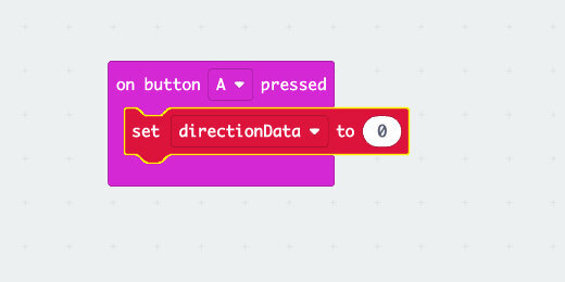
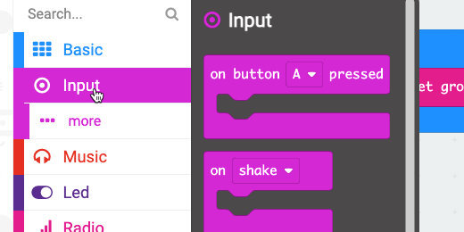
The Micro:bit will collect the data from the sensors when we press one of the buttons. Go to the Input section; find the [on button A pressed] code block.

Place the code block on the workspace.

Go to the Variables section. Get the Set variable code block.

Place the code block into the [on button A pressed] function.
Get another Set variable code block and place it into the button function.

Click the variable selector for the set variable block we just added; select [tempSensorData].

Place another Set variable code block into the button function. Change the variable to [lightSensorData].

We are going to assign a sensor code block to each variable. This will assign the corresponding value from each sensor to the variable.
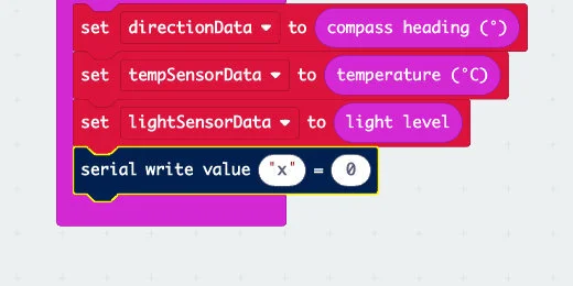
Go to the Input section; find the [compass heading] code block.

Place the code block into the [directionData] assignment parameter.

Return to the Variable section; find the [temperature] code block.

Place the code block into the [tempSensorData] assignment parameter.

Return to the Variable section; find the [light level] code block. Place the code block into the [lightSensorData] parameter.

The code is set to store the sensor information from each sensor. The information for each sensor is temporarily stored in the corresponding variable.
Collecting and recording the data
To record the data we need to send the data from the Micro:bit to the computer. The information is sent along the cable connecting the Micro:bit to the computer. This uses a standard called Serial communication.
Click the Advanced button to reveal more code sections.

Find the Serial code section.

Find the [serial write value] code block.

Place the code block in the [on button A pressed]; place the code after all the other code blocks.
The serial write code block has two parameters. The parameter to the left of the equal sign is used to assign a label to the data placed in the parameter on the right.
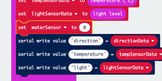
Type “direction” into the label parameter.

Get the [directionData] variable from the Variables section; place it into the right parameter.
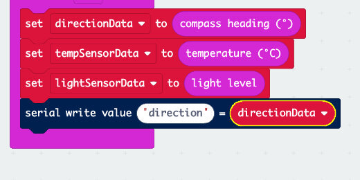
This code block will send the compass heading sensor data to the computer. The data will be given the label “direction”. We will see this in the file later.
Right-click the serial write value code block; select the duplicate option.
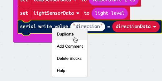
Place the duplicate code block after the current serial write value code.

Click inside the label parameter; change the name to temperature.

Click the variable name selector; choose [tempSensorData].

Duplicate this serial write value code block; place it after the previous code block. Change the label to light. Choose [lightSensorData] from the variable selector.

Compass setup
After pressing the button on the Micro:bit you might be prompted to orient the compass. A message will display across the Micro:bit to tilt the Micro:bit to fill the screen. A smiley face will appear when you have done this successfully.
Upload the code
Whenever we send information from one computer to another it is called uploading. Whenever we receive information from another computer, it is called downloading.
Connect the Micro:bit to your computer. Click the actions menu and select Download to Micro:bit.

There is a Micro:bit simulator on the left side of the workspace. We won’t be using the simulator. Press button A on the real Micro:bit. A button appears under the Micro:bit simulator. Click the “Show console device” button.

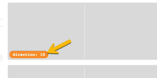
Three scrolling graphs appear in the top part of the console section. The scrolling graphs are used to chart continuous data received from the sensor. Our program is collecting one set of data values at the moment we press the button. No data is plotted on the graphs because we only have one value. The one value collected appears in an orange pillbox.
The bottom of the console page displays all the values collected from each sensor. The values include the labels we assigned in the write value code block.

Students will write these values in a table or open them in a spreadsheet.
The values are available in a CSV file. Click the download button to get a copy of the file.

The CSV file
Opening the CSV file in a spreadsheet shows the data values under each of the corresponding labels. The file includes other columns of information. These labels refer to the time when the data was collected. Each time label is followed by the source label. The time label will always be zero for this program.

Water sensor data
This sensor configuration is optional.
Detecting the amount of water in a potted plant requires two alligator clips and two pieces of wire. The pieces of wire are the probes we stick into the soil. I like to use paperclips because they are found everywhere and a box of them is cheap. The probes don't have to be made from wires; they can be nails or screws.
One alligator clip connects to any available pin. These pins include pins 0, 1, and 2. The other alligator clip connects to the 3-volt connector. The other end of each alligator clip connects to one of the wire probes.
Create a variable; use “waterSensor” for the variable name. Place the Set variable code block into the button A pressed function.
Find the Pins code section under the Advanced codes area.

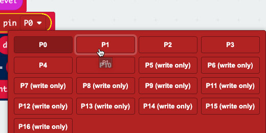
Find the [analogue read pin P0].

Place the code into the variable assignment parameter for the water sensor.

Click the Pin selector; choose the connector where your alligator clip is connected. The options are P0, P1, or P2.
Make a copy of the serial write value code. Change the label to water and the variable to [waterSensor].

Download this code to the Micro:bit. Collect data from all the sensors.
Micro:bit remote sensor
This lesson requires two Micro:bit devices. One is used to collect sensor data from a source. The other is used to receive the data and store it onto a computer as a CSV, Comma Separated Value, file. This lesson demonstrates how we use code within a program to do a lot of tasks for us. Most of those tasks are math-related. This lesson will use math to calculate several variables.

Remote sensor and progress bar
The Micro:bit has a variety of sensors built into the device. It can interface with other sensors connected to contacts on the Micro:bit. This makes the Micro:bit a good tool for science investigations and data collection.
One Micro:bit connected to a computer and collecting data is a common way to gather sensor information. Another way is to pair it with another Micro:bit. In this way, one Micro:bit is used to gather data from a remote source and send the data to another Micro:bit connected to a computer. The data is sent through the Micro:bit Radio. The receiving Micro:bit is connected to a computer to collect data and store it for analysis.
The Micro:bit collecting data may usually be in a location that is not easily accessed or where it would be better not to disturb the data collection process. For example, the transmitting Micro:bit could be on the roof collecting temperature, light, or moisture data. The Micro:bit could be in a bucket of ice-water. It could be outside a window gathering temperature and moisture information. It could be in another classroom with one group of students using the Micro:bit to transmit data to another class.
The lesson objectives
This lesson requires two Micro:bit devices. One is used to collect sensor data from a source. The other is used to receive the data and store it onto a computer as a CSV, Comma Separated Value, file.
I want to take this lesson beyond the fundamentals and include other options. One of those options includes a progress bar. The progress bar is used to provide visual feedback on the device when it is working to collect and transmit data.
This lesson demonstrates how we use code within a program to do a lot of tasks for us. Most of those tasks are math-related. This lesson will use math to calculate several variables.
We are creating two programs. One is for the first Micro:bit to collect and transmit data. The other is for another Micro:bit to receive and save the data to a CSV file.
The project can be used to transmit data from any sensor on the Micro:bit. It can also be used to collect data from a sensor connected to the Micro:bit.
Project previews
Use the links below to see and get a copy of the finished projects. Use them as a resource to check your own finished project.
Micro:bit transmitter (Make Code):
https://makecode.microbit.org/_ViH5R3eX26X3
Micro:bit transmitter (Github):
https://github.com/digitalmaestro/microbitSensorTransmitter
Micro:bit receiver (Make Code):
https://makecode.microbit.org/_86P3iJidxf4w
Micro:bit receiver (Github):
https://github.com/digitalmaestro/microbitSensorReceiver
The project
The programs will be developed using Microsoft Make Code. This is a free online IDE, Integrated Development Environment. Use the link below to access the online IDE. You don’t need an account to create projects.
Click the New Project button.

Use “sensorTransmitter” for the project name; click the Create button.

Every new project includes two code blocks on the coding workspace. These blocks include the [on start] section and [forever] loop.
The [on start] section is used to run code as soon as the Micro:bit starts or is restarted. This is where we usually define variables. We will use plenty of variables in our project.
The [forever] loop runs code for as long as the Micro:bit is powered. Code inside this loop does not require any user interaction. We won’t be using the [forever] loop in this project.
Get the [forever] code block and drag it to the Codes Section. Release the code block when a Trash Can icon appears.

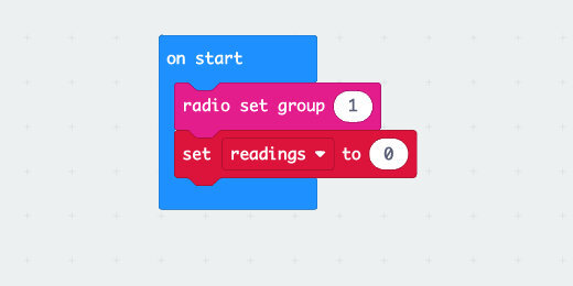
To transmit data we need to activate the Radio on the Micro:bit. Click on the Radio section; look for the [radio set group] code block.

Place the code block into the [on start] section. The Radio set group is automatically set to group 1. We can use any group number from 0 to 255. Group one is a good place to start. The same radio group number must be used on both the transmitting and receiving Micro:bit.

We need to gather data from one of the sensors. We’ll use the temperature sensor for this example. We will create a variable to store the value from the sensor reading.
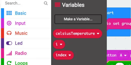
Go to the variables section; click the “make a variable” button.

Use “celsiusTemperature” for the variable name; click the OK button.

Three code blocks are created for each variable. The first is the variable itself. The second is used to set, or assign, a value to the variable. The third is used to change the value of the variable by some numerical increment.

Go to the Input section; find the [on button A pressed] code block.
Place the code block on the canvas.

Get the [set celsiusTemperature] variable; place it into the [on button A pressed] code.
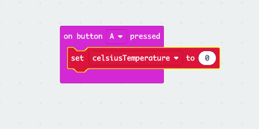
Go to the Input code section; find the [temperature] code.

Place the [temperature] code into the [set celsiusTemperature] code parameter.

When we press button A, the code will query the temperature sensor and store the value into the [celsiusTemperature] variable.
After getting the temperature from the sensor, we need to transmit that information to the receiving Micro:bit. Go to the Radio code section; find the [radio send value] code.

Place the code block into the [on button A pressed] code and after the variable code. Code is processed in the order it is created. We need to get the temperature value before sending it to the receiving Micro:bit.

The send value code block has two parameters. The first parameter is used to provide a name to the numeric data in the second parameter. Type “Celsius” into the value name parameter.

Get the [celsiusTemperature] variable from the variables section; place it into the second parameter for the radio send code.

The code will get the temperature data and transmit it to the other Micro:bit each time button A is pressed.
Multiple readings with loops
We want to automate the process so the Micro:bit collects multiple readings from the sensor and transmits each.
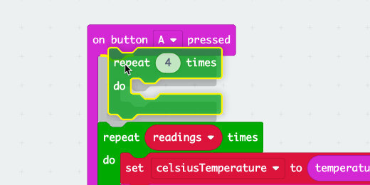
Go to the Loop section; find the Repeat loop.

Move the loop over the [on button A pressed] code. Look at the code shadow and make sure the other code blocks pop inside the loop.

The Repeat loop is set to repeat the code in the loop 4 times. Each loop represents a reading from the sensor and a value sent to the receiving Micro:bit.

We are going to need to gather many more data values over some time. We need a variable to store the number of readings we want to collect. Go to the Variables section. Click the "make a variable" button.
Use “readings“ for the variable name; click the OK button.

Get the [set readings to] code; place it into the [on start] section.
Enter thirty into the assignment parameter for the variable. In this example, we are going to collect thirty readings from the temperature sensor.
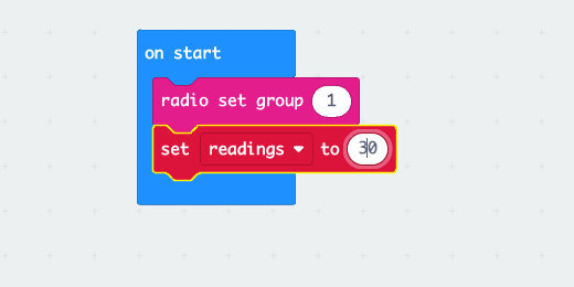
Get the [readings] variable; place it into the loop parameter.

The number of values we want is assigned to the readings variable when the Micro:bit starts. That value is passed into the loop and ready for when we press button A.

The Micro:bit is fast and it processes instructions almost instantly. It will process all the sensor readings in less than a second. We need to slow the process to collect readings from the sensor over some time.
Go to the Basic code section; find the [pause] code.

Place the [pause] code at the end of the code in the loop.

The time intervals are measured in milliseconds.
Click the time selector in the [pause] code. We can choose a time interval from 100 milliseconds to five seconds, which is 5000 milliseconds.

We usually don’t think in terms of milliseconds or even seconds for the most part. We think in terms of minutes or hours. To convert minutes to milliseconds we multiply the number of minutes by 60,000. One minute is 60,000 milliseconds. Five minutes is 300,000 milliseconds. Simple enough, but when we have a computer we can have it do all the work.
Minutes to milliseconds
We will add code to convert the number of minutes we want into milliseconds.
Go to the Variables section. Create a variable and use “minutes” for the name. Create another variable and use “pauseTime” for the name.

Get a set variable code block; place it into the [on start] section. The set code block uses the variable name of the most recently created variable. Mine is set to “pauseTime”.

Click the variable name selector; choose “minutes”.
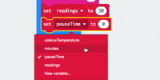
Place another set variable code block into the [on start] section. Select “pauseTime” for the variable.

The pause time variable will calculate the milliseconds for us.
Go to the Math section; find the multiplication operation.

Place the multiplication operation into the set “pauseTime” parameter.

Place the [minutes] variable into the left side of the multiplication operation.

Enter 60000 into the right side of the multiplication operation.
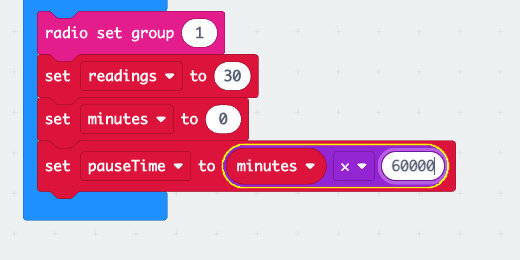
Type the number 1 into the minute's assignment parameter.

Place the [pauseTime] variable into the [pause] parameter.

The loop will pause one minute between readings. With 30 values to gather, it will take half an hour to take all the sensor readings.
To take the same amount of readings in less time we need to calculate the interval between readings. What pause interval do we need to take 30 readings in 20 minutes? We can divide 20 by 30 to give the interval in fractions of a minute. In this example that would be 2/3 or .6667. A reading is taken every 2/3s of a minute.
We don't have to calculate this ourselves. The Micro:bit will work out the math and calculate the correct pause time. It will calculate this time based on the readings we want and the total period.
Go to the Variables section. Create a new variable; use “totalTime” for the variable name.
Place a [set totalTime to] code block in the [on start] section.

We need to reassign the value in the set code we added earlier. The set code that calculates the pause time contains the math to calculate the total time in milliseconds. Click the variable selector and choose totalTime.

Select [pauseTime] in the set variable code block we just added.

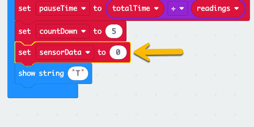
To calculate the pause time we need to divide the total time by the number of readings. We know to divide time by readings because we want to know the pause time per reading or between readings.
Go to the Math section; find the division operation.

Place the operation into the [set pauseTime to] parameter.

Get the [totalTime] variable; place it on the left side of the division operation. Get the [readings] variable; place it on the right side of the division operation.

With these instructions programmed, all we need to do is decide on the number of readings and the period for those readings. The program will calculate the regular time interval between each reading.
Sensor countdown
The sensor will start taking readings as soon as button A is pressed. I like to give myself some time to press the button and place the Micro:bit into the environment to begin taking readings. I like to add a countdown timer.
Go to the Loop section; get a Repeat code block. Place the code block in the [on button A pressed] code and before the current loop.
We need a container to hold the countdown numbers. Create a variable and use “countDown” for the name. Place the [set countDown to] code into the [on start] section. Assign the variable a value of 5.

Type the number five into the Repeat loop parameter.

Get the [show number] code block from the Basic section. Place the code block into the Repeat loop.

Get the [countDown] variable; place it into the [show number] parameter.

Get the [change countDown by] code block; place it after the [show number] code. Change the parameter value from 1 to a negative one(-1).

Get a [pause] block; place it after the change variable code. Set the pause duration to one second.

Get the [clear screen] code block from the Basic section; place it after the [pause] code.

Identify the transmitter
The send code for the first Micro:bit is complete. All Micro:bits look about the same. We need a way to identify this Micro:bit from the receiving Micro:bit.
Place a [show string] code block in the [on start] section.

Enter the letter “T” for the string assignment. This will display the letter “T” until we press the button to begin the data collection.

Progress bar
It’s comforting to see something happening on the Micro:bit to know everything is working. I like to include a basic progress meter.
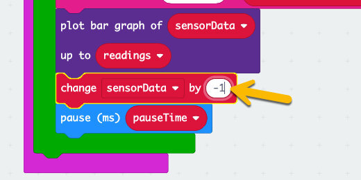
Go to the LED section; find the [plot bar graph of] code.

Place the code after the [radio send value] code.

We need a container to hold the value for the plot. Create a variable; use "sensorData" for the name. Place the [set sensorData to] code into the [on start] section.
Place the [readings] variable into the [sensorData] assignment parameter. The number of sensor data readings is the same number of readings.

Place the [sensorData] variable into the first parameter for the plot data graph code. Place the [readings] variable into the second parameter.

Get a [change sensorData by] code block; place the code after the plot bar graph code. Change the value from one to a negative one(-1).
Test the code
Change the minute assignment value to 1-minute.

Click the button. The Micro:bit simulator will begin with a five-second countdown. The display will fill with light LEDs.

Rows of LEDs will turn off as the data is sent. The count down we created with the sensor data variable is reduced by one each time a value is sent. This is what the graph is plotting.

A progress meter that gets smaller over time is different from your typical progress bar. We can reverse the operation and have the bar grow over time. We are going to use Math to do this!
Remove the [sensorData] variable and set it to one side for a moment.

Go to the Math section; get the Subtraction operation code. Place the code into the plot bar graph parameter.

Place the [sensorData] variable on the right side of the subtraction operation.

Get a [readings] variable; place it on the left side of the subtraction operation.

Press button A to run the program. The bar graph will plot the values going up instead of down.
Change the time to a value that represents the time for the readings you want to collect. Set the number of readings you want to collect during that time.
Download the code to the first Micro:bit.
Receiving Micro:bit
This is the easiest part of the code. The receiving Micro:bit’s job is to receive the data and compile it into a CSV file.
Click the Home button to return to the Make Code for Micro:bit home page.

Click the Create New Project button; set the name of the new project to “sensorReceiver”.

Get rid of the [forever] loop.

Go to the Radio section; get the [radio set group] code and place it on the [on start] section. Make sure the radio group number is the same as that used by the transmitting Micro:bit.

Get the [on radio received name value] code from the Radio section. Place the code on the workspace.

Open the Advanced code section; find the Serial codes section.

Look for the [serial write value] code block.

Place the code block into the [on radio received] code.

The radio received code block contains the information received from the transmitting Micro:bit. This information is stored inside two variables created by the code block. The variables are “name” and “value”
Click the “name” variable and drag it to the parameter on the left side of the equal sign.

Drag the “value” variable onto the parameter on the right side of the equal sign.

variable name being added
This code will collect the data values sent by the other Micro:bit and create a file with the values. The “name” variable represents the title we provided for the temperature, Celsius. The “value” variable contains the temperature values collected from the sensor.

The receiving Micro:bit needs to be connected to the computer while collecting data from the sending Micro:bit. You also need to be on the Make Code IDE site. The site facilitates the collection and compilation of the data into a CSV file.
Download the program to the receiving Micro:bit before pressing the button on the sending Micro:bit.
Plug the other Micro:bit to a power source and press the button. You might need to use a battery in some situations.
A “Show console Device” button appears once the receiving Micro:bit receives the first value. Click the button to watch the data as it is received.
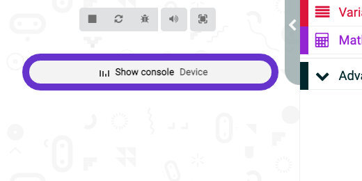
The data received is displayed in the bottom section of the console.
Important: Don’t leave the console page or click on anything else while collecting data. This will interrupt the collection process. You will have to start over if this happens. Press the Restart button on the back of the Micro:bits to start over.

Click the Download button to save the CSV file to your computer when the process is complete.

End notes
The Radio signal from the Micro:bit is not very strong. Lots of things can interfere with the signal. This limits the distance you can be from each Micro:bit to send and receive data. You will need to test for the maximum distance in your environment.
Micro:bit timer
In this lesson, we are going to work on a countdown timer. The timer will count down in seconds, but it can be used for minutes too. We will develop an interface to set the timer value with the A and B buttons. The shake option will be used to reset the timer. We will include a countdown tone.

Timer
In this lesson, we are going to work on a countdown timer. The timer will count down in seconds, but it can be used for minutes too. We will develop an interface to set the timer value with the A and B buttons. The shake option will be used to reset the timer. We will include a countdown tone.
The code for the finished project is available from Make Code and my Github repository; use the links below.
Make Code: https://makecode.microbit.org/_8zzFXgfdg2VM
Github: https://github.com/digitalmaestro/timer
Micro:bit simulator and Make Code
You don’t need a Micro:bit to follow along in the lesson. Make Code offers an Integrated Development Environment, IDE, for the Micro:bit. The IDE includes a Micro:bit simulator. Use the link below to access the Make Code website. You don’t need a login account.
https://makdecode.microbit.org
Click the New Project button.

Use “timer” for the project name; click the Create button.
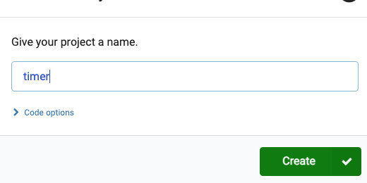
Every new Make Block Micro:bit project includes two code blocks. The [on start] code is used to run code the moment the Micro:bit is connected to a power source or restarted. The [forever] code is part of a function. Code in [forever] is part of a loop that repeats as long as the Micro:bit is connected to a power source.
We don’t need the [forever] function for our project. Take the code block and drag it to the Codes section. Release the block when a Trash Can icon appears.

Basic intervals
We are going to create the timer so that pressing the A and B buttons will allow us to set the timer value. Go to the Input section; find the [on button A pressed] function.

Place the code block on the coding canvas.

We need some variables to store the timer values. Select the Variables section; click the “Make a Variable” button.

Use “intervalOne” for the variable name; click the OK button.

Three code blocks are available for every variable we create.

Get the [change intervalOne by 1] code block; place it in the [on button A pressed] function.

Go to the Basic code section; find the [show number] code.

Place the [show number] code into the [on button A pressed] function and below the variable block.

Select the Variables section. Get the [intervalOne] variable; place it into the [show number] parameter.

This is the basic code for increasing the timer by one unit at a time.
Go to the Simulator section and press the A-button a few times. The value should increase by one each time the button is pressed.

Let’s set up the other button to increase the timer value by 5 at a time. This will save us button presses when we need to set a timer for 10, 15, or more. We will combine this with the A-button to give us other timer values.
Intervals by five
Go to the Input section; get another [on button A pressed] code. Place the code on the coding canvas. The function is faint and a different color. This happens when two button functions are on the canvas for the same button.

Click the button selector; choose button B.

Go to the Variables section; click the “Make a Variable” button. Use “intervalTwo” for the variable name.

Get the [change interval… to ] code block and place it into the [on button B pressed].

Click the variable sector. Choose the [intervalTwo] variable if it is not already selected.

Change the variable interval from one to five.

Get the [show number] code block from the Basic section; place it after the change variable code.

Place the [intervalTwo] variable into the [show number] parameter.

Go to the simulator and press the B-button a few times. The numbers on the display should increase five at a time.

Combining values
The values generated by the A and B buttons are working independently. We need to store the values generated from each button and add them together. We need another variable.
Go to the Variables section; create a new variable. Use “totalTime” for the variable name. Get the [set totalTime to] code block; place it after the [change intervalOne by] code block in the [on button A pressed] code.
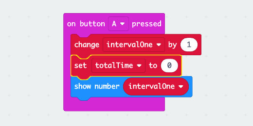
The [totalTime] variable will store the sum of the intervals selected using both the A and B buttons.
Go to the Math code section; find the Addition operation.

Place the Addition operation into the [set totalTime to] parameter.

Go to the Variables section. Get the [intervalOne] code; place it on the left side of the Addition operation.

Get the [intervalTwo] code; place it on the right side of the Addition operation.

Use the variable selector in the [show number] code; choose the [totalTime] variable.

Go to the simulator; press button B once. Press button A two or three times. The values from buttons B and A are added and displayed.

Functions
We need the same cone for button B. Whenever we have code that repeats it is standard to create a Function for that code. The function of our code is to add the value of the buttons pressed for a total timer value.
Select the Advanced code option; select the Functions code section.

Click the “Make a Function” button.

Click inside the function name.

Use “timerTotal” for the function name; click the Done button.

The function is placed on the canvas with the rest of our code.
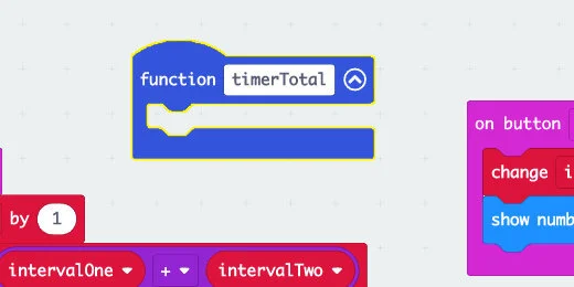
Select the [set totalTime to] code and pull it away from the button function. The [show number] code will be moved too.

Place the code blocks into the [timerTotal] function.

We call the function from the button-pressed code. Select the Function code section; look for the [call timerTotal] code block.

Place the code into the [on button A pressed] and after the [change intervalOne by 1] code.

Get rid of the [show number] code from the [on button B pressed] function.

Insert the [call timerTotal] function into the [on button B pressed] code.

Checking the function
Go to the simulator and press both the A and B buttons. The value on the display will update with the total.
Start the countdown
Once we have the total time for the countdown, we need to begin the countdown. The countdown will be started by pressing both buttons.
Go to the Input section; get an [on button A pressed] code block and place it on the canvas. Use the buttons selector and choose A+B.

Pressing the A and B buttons will begin the countdown process. The countdown uses a loop. There are several ways to use loops. In this program, we want the loop to continue the countdown as long as the countdown value is greater than zero.
Go to the Loops section; find the [while True do] loop.
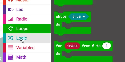
Place the loop inside the A+B button code.

The While loop repeats everything inside the loop while some condition is True or False. In this project, we want the loop to continue as long as the countdown timer is greater than zero. This is a True condition.
To evaluate if something is True, we need a comparison code block. Go to the Logic section; find the Less-then code block.

Place the code block into the While loop parameter.

Click the comparator selector; choose the Greater-than option.
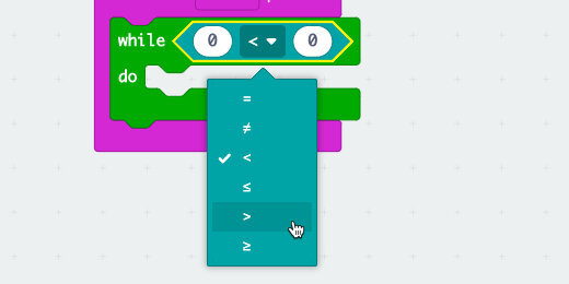
Place the [totalTime] variable into the left side of the comparator.
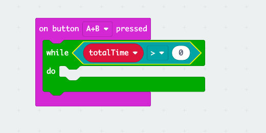
Place the [show number] code block inside the While loop. Get the [totalTime] variable and place it into the [show number] parameter.

Get the [pause] code from the Basic section; connect it to the [show number] code in the loop. Change the pause duration to 1-second.

Get the [change totalTime by] variable block; connect it to the [pause] code. Change the value from a positive one to a negative one.

Test the timer
Go to the simulator; press button B once and button A twice. This creates a seven-second timer.

Click the A+B button. The timer counts down and stops at number one.
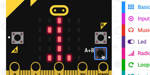
This happens because the loop is instructed to repeat the process as long as the [timerTotal] is greater than zero. Change the comparison operation; select Greater-than or Equal-to.

Set a timer value of your choosing: click the A+B buttons. The timer will countdown and stop at zero.

Set the startup variable values
It’s a good idea to include a way to reset the value without pressing the reset button on the back of the Micro:bit.
Before creating the reset code, we need to set the start-up values for all the variables. Setting the initial values for variables at the beginning is always a good idea.
Go to the Variables section. Place a [set variable to] code block into the [on start] section for each variable. Leave the value assigned for each at zero.

Place a [show number] code block after the set variables code blocks. Place the [totalTime] variable into the [show number] parameter. Place a [pause] code block after the [show number] code; set the pause duration to 500ms. Place a [clear] screen code block after the [pause] code.

This is the same code we are going to use when resetting the timer. We are going to reuse code; this is an indicator that we need a function.
Reset function
Go to the Functions section; click the Make a Function button.

User “clearTimer” for the function name; click the done button.

Get all the code blocks from the [on start] section; place them into the [clearTimer] function.

Click the chevron next to the function name. This collapses the function. The function works in the same way, but all the code is neatly tucked away inside.

Get the [call clearTimer] code; place it into the [on start] section.

Reset on shake
Go to the Input section; find the [on Shake] code block.
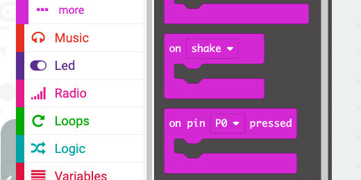
Place the [on shake] code block on the coding canvas. Get a [call clearTimer] block and place it into the [on shake] code.

Test the shake function
Press the B-button three or four times; click the Shake button.

Recall timer value
When using the timer we may want to check the value one more time. The timer value has disappeared from the screen. We need a way to recall the information. The problem is that we have run out of buttons on the Micro:bit. Micro:bit version 2 uses the logo as a contact button. The contact button in version 2 is like the contacts at the bottom of the other Micro:bits. We will use contact number 2 as a contact button.

Go to the Input section; find the [on pin 0 pressed] function. Place the function on the coding canvas.

Click the pin selector; choose pin P2.

We don’t need to create any code to display the timer value. We already created that code and put it in the [timerTotal] function.

Place the [call timerTotal] code into the [on pin P2 pressed] function.

Set a value in the Micro:bit simulator.

Click the P2 contact. It works as a button now.

The contact will change color to show it has been clicked. The value will scroll across the display.

Sound
Version 1.3B and 1.5 of the Micro:bit don't include a speaker. To use sound with these Micro:bit versions, you will need to connect a small speaker.
You can use a larger speaker if you don’t have small speakers. The Micro:bit does not put out enough current to power large speakers. The speakers need to be powered by an external source. There are plenty of portable speakers available on the market. The speakers need an input jack for connecting a 3.5mm stereo cable. These cables have three sections. The sections are separated by a plastic ring. You will need to connect the alligator clips to the first and third sections of the plug. The Micro:bit simulator shows how to connect the clips.
Go to the Music section; find the [play tone Middle C for 1 beat] code block.

Place the code block into the [on button A+B pressed] function. Place the code block after the [show number totalTime] code.

Change the beat from a Whole note to a Quarter note.

Click in the Tone parameter; select Middle-A using the virtual keyboard.

The Micro:bit simulator shows how to connect the audio cable with alligator clips.

Use the simulator to set a timer and test the code using sound.
Download the code to the Micro:bit and start using the timer.
Seconds to minutes
The timer counts down the value we choose in seconds. We may want to use minutes instead of seconds. The Pause code uses milliseconds. One thousand milliseconds is one-second. Sixty-thousand milliseconds is one minute. Enter this value into the [pause] code.

Micro:bit temperature sensor data collection
In this lesson, we are going to transfer data from the Micro:bit temperature sensor directly to our computer. This is a good introduction for the collection of data from Micro:bit sensors. The Micro:bit will collect sensor data. The data will be saved to a CSV, Comma Separated Value, file. The CSV file can be imported into any spreadsheet program. We will import the file into a Google Sheet and create a line chart.

Sensor data
The Micro:bit has a variety of sensors. They are an excellent way to collect data for science investigations. I like the temperature sensor. It provides immediate feedback for something that students can readily relate to. The temperature sensor is a good way to investigate a variety of science concepts.
In this lesson, we are going to transfer data from the Micro:bit temperature sensor directly to our computer. This is a good introduction for the collection of data from Micro:bit sensors. The Micro:bit will collect sensor data. The data will be saved to a CSV, Comma Separated Value, file. The CSV file can be imported into any spreadsheet program. We will import the file into a Google Sheet and create a line chart.
Use the links below to get a copy of the project.
Make Code: https://makecode.microbit.org/_fkxHWh6LWbYg
Github: https://github.com/digitalmaestro/temperature-sensor-data
Micro:bit simulator and Make Code
Make Code offers an Integrated Development Environment, IDE, for the Micro:bit. The IDE includes a Micro:bit simulator. Use the link below to access the Make Code website. You don’t need a login account.
https://makdecode.microbit.org
Click the New Project button.

Use “temperature sensor data” for the project name; click the Create button.

Go to the Input code section; get the [on button A pressed] code and place it on the coding canvas.
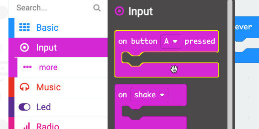
Go to the Variables section; click the "Make a variable" button.

Use “celsius” for the variable name; click the OK button.

Three code blocks are available for every variable. The first is the variable itself. The others include the set variable code block. This assigns a value to the variable. The other is the change variable code block. This code increments the value of a variable by a value of our choosing. This block is often used in counting and loops.
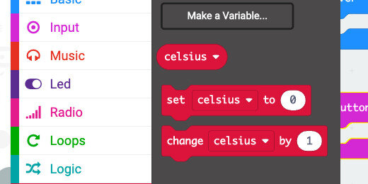
Get the [set celsius to] code block; place it in the [on button A pressed] function.

Go to the Input code section; find the [temperature] code block.

Place the code block into the [celsius] assignment parameter.

Go to the Basic code section; find the [pause] code block.

Place the [pause] code block below the [set celsius to] code.

Use the time selector; select 1-second.

Click the Advanced menu to display the advanced code blocks.

Select the Serial code section.

Find the [serial write value] code block.

Place the code block before the [pause] code.
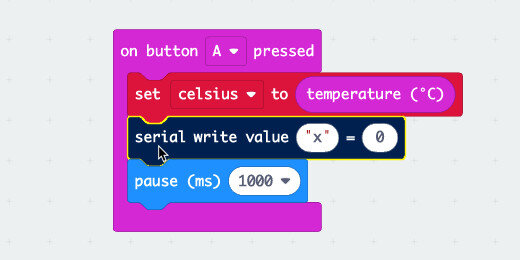
Type "celsius" in the value description field.

Go to the Variables section. Get the [celsius] variable; place it into the [serial write value] field.

This code will set the temperature sensor information and save it to the [celsius] variable. The value in the variable will be passed into the [serial write value] code. The serial write value code writes the values into a CSV file, which we will save later.
The code includes a one-second delay. We will use this delay later to collect sensor readings.
Go to the simulator area; press the A-button.

A simulated temperature meter appears on the Micro:bit. This represents fake temperature data.

A “Show console Simulator” button appears below the Micro:bit simulator; click the button.

The simulator includes a scrolling graph of the data collected by the sensor. The simulated sensor has collected one reading so there is no chart to create.

The values recorded by the program are shown in the section below.

Click the “Go back” button to return to the coding environment.

Device sensor information
We want to collect information from the real Micro:bit sensor. Connect your Micro:bit to the computer.
For the next step, I'm going to assume you have not paired your Micro:bit to the computer.
Click the more menu option; the three dots. Select the Pair device option.

Click “Pair device” when the instruction box opens.

Your browser might ask you to select the device to pair. Select the Micro:bit device and click the Connect button.

Click the More Actions button; select “Download to micro:bit”.

Don’t disconnect your Micro:bit from the computer. Click the A-button on the real Micro:bit.
A “Show console Device” button appears below the Micro:bit simulator; Click the button.

We have collected only one value, so the graph doesn’t show anything of interest.

The data area shows the first value collected by the Micro:bit. The temperature collected by my Micro:bit sensor is 27-degrees celsius.

Press the button on the Micro:bit a few times. Place the Micro:bit in your hand or on objects with different temperatures. Press the button each time to get a new temperature reading.
My Micro:bit recorded eight sensor readings. Five readings measured 27-degrees, two readings measured 28-degrees, and one measured 29.

The scrolling graph displays the changes in sensor readings over time.

Click the “Go back” button.
Collect multiple readings
Pressing the button to get a temperature reading is fine, but it is not the best way to get continuous readings from a single source. We are going to add some code so the sensor will get temperature readings at regular intervals.
Get the [repeat times] loop from the Loops section.

Move the loop into the [on button A pressed] function. Make sure the loop surrounds and incloses the existing code.

Change the repeat parameter from 4 to 60.

The [pause] code we added earlier is set to one second. Readings will be taken from the temperature every second. The program will do this 60 times. That gives us one minute's worth of temperature data.
Click the actions menu and download the program to the Micro:bit.

Press the A-button on the Micro:bit. Click the Show console Device button.

Temperature readings from the sensor will begin to be recorded. My Micro:bit is on my desk and reading the same temperature for every reading. It will stop taking readings when the number in the loop parameter is reached.

Ice water temperature
This is a simple way to test the program and collect data.
CAUTION!
PERFORM THIS PART OF THE LESSON ONLY IF YOU HAVE A WATER-TIGHT BAG FOR THE Micro:bit.
Get a bowl of water and add ice. Place the Micro:bit into a water-tight bag. I use a water-tight bag for cell phones. The bag is rated IPX8. This means the bag can be dropped into the water and the bag will not let water in for some time.

Press the A-button on the Micro:bit and submerge it into the ice water. I could not close the bag because of the cable so I held the top of the bag while the Micro:bit was in the ice water.

Click the Show console Device button. Watch as the sensor data is collected and displayed. The numbers in the grey represent the number of readings at that temperature. Each temperature has several identical readings. This is because we are taking one reading every second.

Watch the scrolling graph. The data collection is complete when the graph stops displaying the collection of data.

The data has been collected and temporarily stored in a text file. We need to download this file before anything else. Click the blue arrow to download the CSV file.

More temperature data
Taking a temperature reading every one-second might have been too much. Return to the code; change the pause duration from one to two seconds.

Click the actions menu and download the updated code to the Micro:bit. We always need to download any changes to the Micro:bit.

Repeating the experiment
Take the Micro:bit out of the ice water and pouch between measurements. Leave the Micro:bit out for about 5 minutes. This will give the Micro:bit some time to warm up to room temperature. Place the Micro:bit into the pouch after five minutes, press the button, and insert the Micro:bit into the ice water.
The process will take about two-minutes this time. Watch the graph being plotted and the data being collected. Download the CSV file when the process is complete.
Repeat the process one more time. Return to the code and change the pause duration to five-seconds. Download the updated code to the Micro:bit. Insert the Micro:bit into the ice water and collect the data. The process takes five minutes this time.
Note that we are taking the same number of readings. The only thing that is changing is the duration between readings. How does the duration relate to the data retrieved from the Micro:bit?
Importing data to Google Sheets
By now you should have at least two CSV files with temperature data. Open a new tab in your browser and create a new Google Sheet. The link below will take you to Google Sheets and create a new sheet. You will still need to log in with your account.
https://sheets.google.com/create
Click the sheet name; rename it to Micro:bit temperature data.

Click File and select Import.

Select the Upload option.

Click the “Select a file from your device” button.

Select the first CSV file; click the Open button.

An import configuration box opens. Select the option to replace the Sheet.

Leave the other options set to detect the separator type automatically and convert the information automatically. Click the Import Data button.
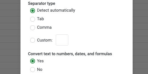
The data includes some heading information. Erase the contents of the first cell, cell A1. Change the title for the time to "Time(seconds)". Update the title for celsius. Have it begin with a capital letter.
The first data value was taken at the moment we pressed the button. It was taken at zero seconds. We don’t need this data value. Select the cells and delete the information.

Select the cells with the data collected; include the headings.

Click the insert a chart button.

You should get a basic line chart.

Import more data
We will use the same sheet to import other data values.
Deselect the cells; click File and select Import.

Choose the Upload option and select the next CSV file. Choose the Insert new sheet(s) option from the import file configuration box. Click the Import data button.

Double click the sheet name; use “2 seconds” for the sheet name.

Cleanup the heading information like we did with the other import. Create a chart with the new data.
Repeat the process if you collected data from the sensor using five-seconds for the pause duration.
Use the link below to get a copy of the data I collected and uploaded to Google sheets. The first link gives you a preview. The second link will allow you to save a copy of the sheet to your Google Drive.
Micro:bit progress bar for data collection projects
This lesson creates codes for a progress bar. Progress bars are a good way to get feedback during an operation. The Micro:bit has a variety of sensors. Those sensors are an excellent way to collect data for science investigations. The collection of data can take some time. The duration can be a few minutes or more. During that time we don’t have visual clues to provide feedback on the data collection progress. This is where a progress bar is something useful to include in a project.

Micro:bit progress bar
The Micro:bit has a variety of sensors. Those sensors are an excellent way to collect data for science investigations. The collection of data can take some time. The duration can be a few minutes or more. During that time we don’t have visual clues to provide feedback on the data collection progress.
This is where I decided it would be a good idea to include a progress bar when a Micro:bit is tasked with collecting data. The data can be like a vessel that is filled with a specific amount of information. For example, we might want to collect several measurements as they are coming in from the accelerometer. In another example, we might want to collect the ambient temperature in a room over some time.
The code for this progress bar can be used in a variety of projects. I have a couple of projects in the works where the progress bar will be part of the project.
Programmers often keep libraries of code they can use in a variety of projects or applications. This code will be one of our library resources for use in future projects.
In the lesson, you will learn how to use variables to keep track of information. If you are an educator, you will have the opportunity to demonstrate how math proves to be a useful tool in coding. The project uses basic division, addition, and multiplication. The project refers to the coordinate plane. The coordinate plane is a little different from that used in traditional math, but it does use the same x and y-axis properties.
Use the links below to get a copy of the finished project and the basic progress bar project.
My progress bar(Make Code): https://makecode.microbit.org/_APVgej8KFfW5
My progress bar(Github): https://github.com/digitalmaestro/my-progress-bar
Basic progress bar(Make Code): https://makecode.microbit.org/_8AP8P5546E2i
Basic progress bar(Github): https://github.com/digitalmaestro/a-basic-progress-bar
Micro:bit simulator and Make Code
You don’t need a Micro:bit to follow along in this project. Make Code offers an Integrated Development Environment, IDE, for the Micro:bit. The IDE includes a Micro:bit simulator. Use the link below to access the Make Code website.
https://makdecode.microbit.org
Click the “New Project” button.
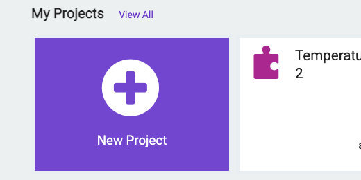
Use “My Progress Bar” for the project name; click the Create button.

A progress bar is based on the measurable completion of a process. The measurement is taken as either a counter toward the completion or as a percentage of the complete process. We are going to use a simple counter to generate the progress bar.
In a project, we are likely to collect a specific number of values from a sensor over a given period. In this example, we are going to use the temperature sensor to collect data. We are going to query the sensor every two minutes. The period can be longer or shorter. The progress bar works the same regardless of the number of values collected.
The Micro:bit has five LEDs across and five down. The five LEDs across will be used to represent the progress bar. The progress bar will light up across the middle of the Micro:bit. The number of values we decide to collect needs to be divided into equal units represented by each of the five LEDs. We can take care of this with a simple division.
To understand how this progress bar works, let's take a look at some examples. We want to take 30 temperature measurements over some time. The time does not matter in this example. We need five markers in those thirty measurements to use for the progress bar. Thirty divided by five is six. An LED will light along the progress bar every time we reach a count that is divisible by six.
While counting we need to compare the count to a marker divisible by six. The table below shows six multiplied by one; then multiplied by two; then three; four; and finally five. The answers for each represent a value we will use to activate one of the LEDs. The first LED will light when the counter reaches six. The second LED will light when the counter reaches 12. The process continues until the counter reaches 30.

The same holds if we choose a different number of sensor readings. In this next example, we are collecting 80 readings. The table shows the divisions and values for each division. Eighty divided by five is sixteen. This number is multiplied by five, then four to one in the table.

The values are different for each number. The difference is not an issue. We are using an algorithm to activate each LED regardless of the value.
The difference between each stage increases as the number of values collected increases. This will trigger each LED to be light for a long time before the next lights. We will take care of this by instructing each LED to blink while data is being collected during each stage.
Go to the Variables section; click the “Make a variable” button.
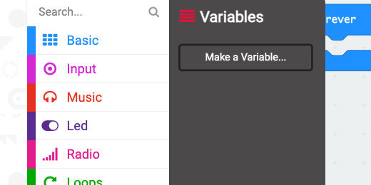
Use “totalCount” for the variable name; click the OK button.

Make another variable; use “unit” for the variable name.
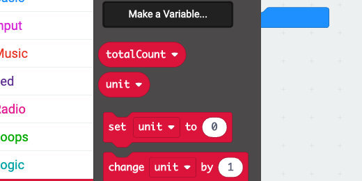
Three code blocks are created for each variable. The first is the variable block itself. The other variables set the value of a variable and change the variable by some value.
Place the [set variable to] code block into the [on start] section.

Place another [set variable to] code into the [on start] section. Click the variable selector for the first code block and choose the [totalCount] variable. Make sure the second is set to the [unit] variable.
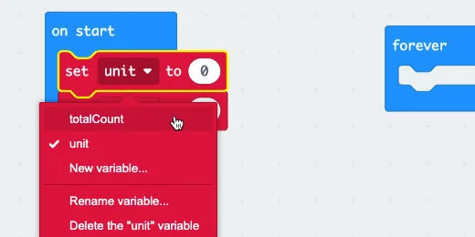
The [totalCount] variable represents the number of values we want to collect from the temperature sensor. Enter 30 in the variable assignment parameter.

The [unit] variable will hold the value when we divide five into the total number of measurements we want to collect. In math, this is referred to as the Quotient. The quotient is part of the pattern of numbers used in the progress bar.
Go to the Math section; find the division operation.

Place the division operation into the [unit] variable parameter.

Get the [totalCount] variable; place it into the left side of the division operator.

Enter the number five into the right side of the operator.

We need another variable. This variable will be used as the container to keep track of the count.
Go to the Variables section; create a new variable. Use “counter” for the variable name. Place the [set counter to] code into the [on start] section.

Go to the Input section; get the [on button A pressed] code and place it on the coding canvas.

We are using a loop to keep track of the readings and values collected. The loop will generate a progress bar as long as the counter is less-than or equal-to the total number of values we want to collect. The number of values is 30 in our current example.
Go to the Loops section; get the [while True do] loop and place it into the [on button A pressed] function.

The [while True do] loop will process the contents of the loop while a condition is True. Our condition will be that the counter is less-than or equal-to the [totalCount] value.
Go to the Logic section; get the less-than comparison code block.

Place the comparison block into the loop parameter.

Click the comparator selector; choose less-than or equal-to.

Get the [totalCount] variable and place it on the right side of the comparison code.

Get the [counter] variable and place it on the left side of the comparison code.

The loop will process the code inside the loop as long as the counter is less-than or equal-to the total count. The total number of readings we want to get from the temperature sensor.
Place the [change counter by 1] variable block into the loop. This adds one to the counter each time the loop cycles.

Go to the Logic section; find the [if True then] condition.

Place the condition into the loop. Place it before the [change counter by 1] block.

The code inside a condition is executed if the requirements for the condition are met. The condition needs something to evaluate. One way to evaluate something for a condition is to make a comparison. For example, if something is equal to something else, then run the code in the condition.
Go to the Logic section; get the Equality comparison code block.

Place the comparison code block into the Condition parameter.

Place the [counter] variable into the left side of the Equality comparator.
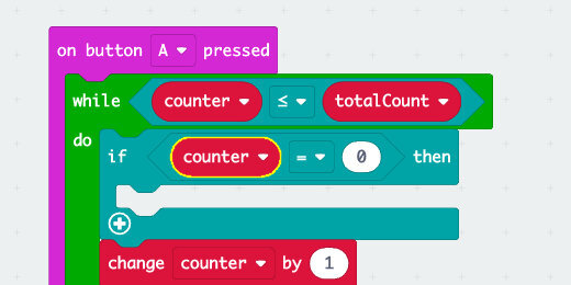
The other side of the comparison code uses basic math. We need five points to check for comparison. Each is related to one of the LEDs to be light.
In the [on start] section we calculated the units of the division by the 5 segments we need for the LEDs. Multiplying the Unit or quotient(6) by 1, 2, 3, 4, and 5 will generate the markers we need.
Go to the Math section; find the multiplication operation.

Place the multiplication operation on the right side of the comparison code.

Place the [unit] variable into the left side of the multiplication operation.
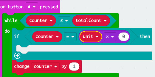
The unit value needs to be multiplied by each number from 1 to 5 for comparison to light each LED in turn. Type the number 1 into the right side of the multiplication operation.

When the counter and the unit values are the same, the first LED will light. Go to the LED section; find the [plot x… y…] code block.
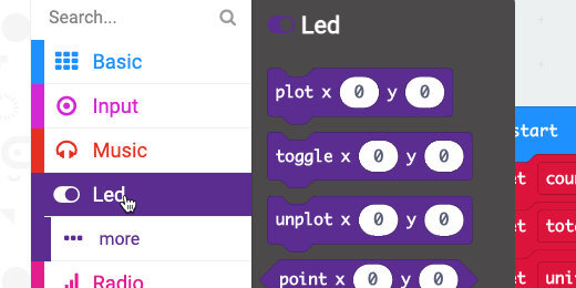
Place the code inside the condition.

The LEDs are numbered using the computer Index. Computer indexes begin with zero. All the LEDs on the Micro:bit begin at index zero from left to right and top to bottom. The LED at index x=0 and y=0 is the top left LED. The progress bar will begin in the third row. This is index zero for the x-axis and two for the y-axis.
Enter the number 2 for the y-axis value.

The LEDs will be light from left to right. The next LED to be light is along the x-axis. The set of index values for the next LED are x=1 y=2. The y-axis index will always be the same.
This is the basis for lighting each of the LEDs in turn. When the counter reaches 12, 6 x 2, the next LED, x=1 y=2, will light.
The numbers for the multiplication and the x-axis index increase by one during each cycle. This is a clue for us to use a counter and a loop.
New programmers often want to repeat a process. For example, we could make a copy of the condition statement and change the values for the next LED(don’t do this part). In the image below, I duplicate the condition statement, changed the multiplication value from 1 to 2, and changed the x-axis index to 1. This involves unnecessary repetition of code. If we ever needed to update the code we would need to update each condition. For example, if the next version of the Micro:bit included a 7 by 7 matrix of LED lights. We would need to add two more conditions and change the numbers.

This is what we will do instead.
Go to the Variables section. Create a new variable; use “ledCounter” for the variable name.

Place the [ledCounter] variable on the right side of the multiplication operation.

Place the [set ledCounter to 0] block into the [on start] section.

The [ledCounter] will be used in a multiplication operation. Multiplying anything by zero will result in a zero. There are times when we might want that, but not in this situation. Change the assignment value to number one.

Plotting the LED uses a similar process. We need to change the x-axis index after each LED is light. Go to the Variables section. Create another variable; use “x-ledplot” for the variable name. Place the variable into the x-axis parameter.

Place the [set x-ledplot to] code into the [on start] section.

Place the [change x-ledplot by 1] code into the condition statement. Place the code after the code to plot the LED light. This changes the value after the previous LED is light.

Place another [change variable by] code block into the condition statement. Change the variable to [ledCounter].
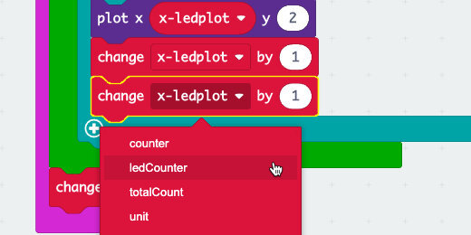
Reviewing the code
When the counter matches the markers, the condition statement will run the code inside. Let’s walk through a couple of steps.
The counter will increase by one each time through the loop until it reaches the first marker at six. The LED at the positions x=0 and y=2 will light. The [x-ledplot] variable will increase by one. The [ledCounter] variable will also increase by one.
During the next series of loops, the counter will need to match the product of the Unit variable times two. When the counter matches 12, the LED at positions x=1 and y=2 will light. Each of the variables will increase by one. The process will continue until the counter reaches the value of 30.
One more thing
Move the [change counter by 1] code block; place it after the condition statement and in the loop.

Running the program
The progress bar code is complete. Click the A-button.
The code generated the progress bar but it did so a little too fast. Get a [pause] code block from the Basic section. Place it below the condition statement and before the change counter code block.

More data points
The progress bar works with any number of data points we want to collect. Change the [totalCount] variable with another value. For example, enter 80 and click the A-button.

The progress bar takes a little longer to render. That’s because we are collecting more values between each marker.
Collecting temperature values
We can add any operation after the pause code. Create a variable; use “temperature” for the variable name.
Place the [set temperature to] code before the pause code.

Go to the Input section. Get the [temperature] code and place it into the [set temperature to] parameter.
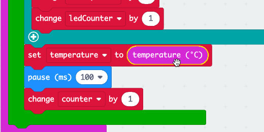
Go to the Radio section; find the [radio set group] code.

Place the code into the [on start] section.

Find the [radio send value ] code block.

Place the code block after the [set temperature to ] code.

Change the value name to Celsius.

Get the [temperature] variable; place it into the [radio send value] assignment parameter.

Change the pause value to 1-second.

Change the [totalCount] variable assignment to 30.

This code will collect temperature information. It will get a new reading every second. The reading will be transmitted to another Micro:bit. It will do this for a total of 30 times, 30-seconds. The progress bar will keep track of the process.
Blinking progress
Collecting move information from the sensor requires more time. The progress bar, in turn, takes longer. It could seem like the progress might have stalled. We are going to include a toggle process in the code each time the loop cycles. A toggle will turn the LED Off if it is On or On if it is Off.
Go to the Logic section; get an [if True then] code block. Place the code after the [if True then] in the loop.

We are using a similar comparison to the one used in the condition above. We can copy all the blocks in this comparison. Move your mouse over the code. Look for the comparison code block to be highlighted.

Right-click when the comparison code is highlighted; select the duplicate option.

Get the code and place it into the condition parameter.

Change the Equality operator to less-than or equal-to.

Go to the LED section; get the [toggle x… y…] code block.

Place the code block into the condition statement.

Get the [x-ledplot] variable; place it into the toggle x-axis parameter. Enter two for the y-axis parameter.
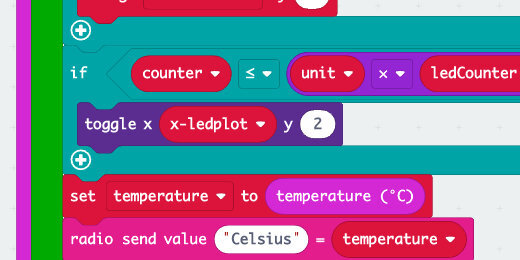
Run the program. Each LED in the progress bar will blink until the counter reaches the required value.
We can reuse this code for other projects. All we need to do is replace the information we want to gather.

Micro:bit temperature transmitter
This project uses two Micro:bits. One will record the ambient temperature and the other will receive and display the temperature. This allows us to remotely monitor the temperature from one Micro:bit. This is useful if you don't want to constantly pick up the Micro:bit from its location to get a reading.

Temperature transmitter
This lesson builds on a previous lesson for a temperature sensor. You don’t need to go through that lesson to follow along with this lesson.
In that lesson, we created a thermometer to read the ambient temperature. The thermometer reports the temperature in Celsius or Fahrenheit when the A or B button is pressed.
The thermometer provides continuous feedback on the ambient temperature. It displays a happy face when the temperature is comfortable, an angry face when it's too hot, and a sad face when it is too cold. Use the link below to access that lesson.
This project uses two Micro:bits. One will record the ambient temperature and the other will receive and display the temperature. This allows us to remotely monitor the temperature from one Micro:bit. This is useful if you don't want to constantly pick up the Micro:bit from its location to get a reading.
The purpose of the project is to be able to monitor the temperature of a location from another location. For example, we can place one the sensing Micro:bit outdoors. The other Micro:bit can be inside a classroom. We can monitor the outdoor temperature from inside the classroom.
Here are some other ways we can use this project. The sensing Micro:bit can be placed into a refrigerator, a freezer, in a sealed plastic bag, and hot water.
We can use it in a science experiment with ice water and salt. Get a container, 1 or 2 gallons; add water and ice in equal amounts. Place the Micro:bit thermometer into a water-tight container like a plastic bag. Measure the temperature until it can't get any colder, around 32-degrees Fahrenheit 0-degrees Celsius. Add salt to the ice water and gently stir. The temperature will begin to drop. This combination can bring the temperature down to minus 6-degrees Fahrenheit. Colder than the freezing temperature of the water.
I recommend a good water-tight container for electronics if you plan to place the Micro:bit into the water. I use a water-tight pouch designed for cell phones. It's large enough to accommodate the Micro:bit and battery. There are plenty of sources available through online retailers. Make sure the pouch has an IPX7 or IPX8 rating. IPX7 items can be submerged up to 1 meter for 30 minutes. IPX8 can be submerged deeper than a meter and can be in the water longer.
The thermometer
Use the link below to get a copy of the thermometer program created in the Thermometer / Thermostat lesson.
https://makecode.microbit.org/_CTiWy7U3qPMe
Github https://github.com/digitalmaestro/thermometer-thermostat.git
The thermometer reports the temperature in Celsius when the A button is pressed. It reports the temperature in Fahrenheit when the B button is pressed. In the Forever loop, it is providing constant information on the ambient temperature. It provides feedback in the form of icon expressions.
Transmitting and receiving
The same code works for transmitting and receiving information. To transmit and receive information between Micro:bits, we need to use code in the Radio section. Select the Radio section.

The Micro:bit needs to pair with another Micro:bit to send and receive information. This is done using the [radio set group] code block. Get the code block and add it to the [on start] function.

The radio group is set to one automatically. The group number can be any number from 0 to 255. The important thing to know is that the communicating Micro:bits must be using the same group number. Leave the radio group set to one.
Go back to the Radio code section and find the [radio send number] code block.

Place the code block after the [set Fahrenheit to…] code in the [forever] loop.

I am using Fahrenheit for the example; we can just as easily send Celsius information.
Go to the Variables section; get the Fahrenheit variable and place it into the [radio send number] parameter.

At this point you will notice a second Micro:bit appears in the simulator section. This is all the code we need to begin transmitting and receiving.

Now we need a way to receive the information. Find the [on radio received(receivedNumber)] code block in the Radio section.

Place the code block on the canvas. The code we place in the function decides what we do with the information received. We will just display the information for now.

Go to the Basic section and get the [show number] code block.

Pace the code block into the [on radio received(receivedNumber)] function.

To show the number from the transmitting Micro:bit, we need to pass the received value into the parameter. The function has a variable to place into the parameter. The variable is called [receivedNumber] and it is in the [on radio received] parameter.

Select the variable from the parameter and place it into the [show number] parameter.
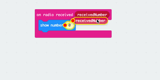
These are all the modifications we need to send and receive data from the thermometer.

Go to the simulator section. Adjust the temperature input slider. Make it hotter by sliding it up.

The first Micro:bit shows the proper icon, angry. The other Micro:bit still shows a happy face. The information is transmitted and received but there is a conflict. The second Micro:bit has a temperature sensor too. The code is getting the readings from that sensor and displaying a happy face.
Receiver only
We built both transmitter and receiver into the same code. I did this so you could see how it works in one example. We are going to modify the code a little to make one Micro:bit into a receiver only. The other will be a transmitter.
The receiver does not need to send information. We don’t need the [radio send number] code.
The code is between other code blocks. Hold the Option key on your keyboard while pulling the code out. The Option key isolates this one block from the others for movement.

Take the code block to the codes section to remove it from the program.

Receiver variable
The receiver is set to record the ambient temperature from the receiver itself. This needs to be changed to display the information received from the transmitter. To do that we need a variable to hold the data from the transmitter. The variable will replace the sensor reading code, [temperature].
Go to the Variables section; click the Make a variable button.

Use “transmittedTemp” for the variable name; click the OK button.

Get the [set transmittedTemp to] variable.

Place the code block into the [on radio received] function.

Remove the [show number] code block.

Place a copy of the [receivedNumber] variable into the [set transmittedTemp] assignment parameter.

The variable will contain the temperature reading sent from the transmitter. We need to replace all the [temperature] code blocks with the [transmittedTemp] variable.
Go to the A Button function. Remove the [temperature] code block from the [set variable to] parameter.
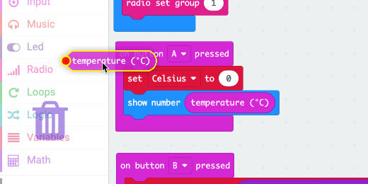
Get the [transmittedTemp] variable from the Variables section; place it in the parameter where we removed the [temperature] code.

Remove the [temperature] code from the [show number] parameter.

Place the [transmittedTemp] variable into the [show number] parameter. Repeat the process for all instances of the [temperature] code.

Don’t forget the one in the [forever] loop.

Receiver only
This Micro:bit is only a receiver now. It does not get information from the temperature sensor. The temperature slider is not on the Micro:bit anymore. If the slider is still there, make sure you replaced all the [temperature] code with the [transmittedTemp] variable.

Rename the project
Go to the project name field and update the name. Use “Thermometer Receiver” for the name.

Transmitter code
We need a separate project for the transmitter. Use the link below to open the Make Code site in a new tab. Create a new project. Use Thermometer transmitter for the project name.
Go to the Radio section. Get the [radio set group] code; place it into the [on start] function.

Get the [radio send number] code; place it into the [forever] loop.

Go to the Input section; find the [temperature] code block.

Place the code into the [radio send number] parameter.
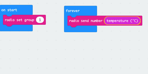
This is all the coding the transmitting Micro:bit needs. The code on the receiver will take care of converting the values to Fahrenheit. The A and B buttons will do their thing.
Too much information
The receiver code includes the comfort zone display. This is not always needed. There is no need to get rid of it. We can make the comfort zone display optional. Using the A+B buttons we will toggle the display code on or off. It will be off when the Micro:bit starts and turned on when buttons A+B are pressed. This will give you the option to get continuous feedback or not.
The code in the forever loop is already lengthy. Whenever we have a block of code that serves a specific function, that is the time we need to place it into a Function.
Click the Advanced option in the code section; select the Functions section.

Click the “Make a Function” button.

A function configuration box opens. Click once inside the function name.

Use “comfortDisplay” for the function name; click the done button.

Move the Function container next to the [forever] loop.

Select the first block in the [forever] loop; move it to the function.

Click the Minimize button.

This collapses the function so the code is neatly tucked away.

Go to the Variables section; click the “Make a variable” button.

Use “toggle” for the variable name; click the OK button.

Get the [set toggle to] code and place it on the canvas.

Go to the Logic section; get the [if True then] condition statement. Place it on the canvas.

Place the [set toggle to] code into the condition code.

Go to the Input section; get the [on button A pressed] code and place it on the canvas.

Place the condition statement into the button function.

Click the button selector; select the A+B option.

The condition needs to check the toggle value. If the toggle is zero, then the Micro:bit will NOT display the comfort symbols. This will be the state when the Micro:bit starts.
To evaluate the condition, we need a comparator. Go to the Logic section. Find the Equallity comparator.

Place the comparator into the condition parameter.

Go to the variables section. Get the [toggle] variable; place it into the left side of the comparator.

Change the value of the [set toggle to] variable; use 1 for the value.

Hang in there!
This is what is going on up to this point. When we press the A and B buttons the condition statement will check the value of the toggle. The value is set to zero when the Micro:bit starts. —We will set this in a moment.— If the value is zero then it will change the toggle value to 1. The 1 instructs the code to display the comfort zone information. The number zero is the Off switch and the number 1 is the On switch.
Back to our code
Pressing the A and B buttons will display the comfort icons. Pressing the buttons again will hide them. That’s what a toggle does.
Click the Plus button in the [if True then] condition.
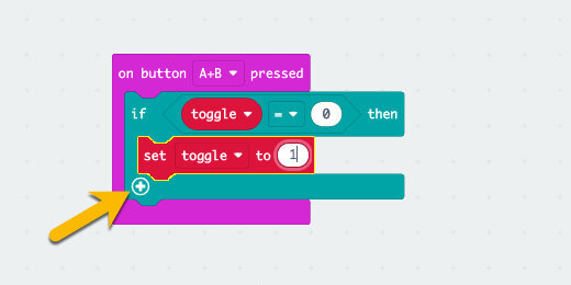
This adds an Else option to the condition.

Go to the Variables section; get a [set toggle to] code block. Place it into the Else section.

This is what the code does. If the toggle value is zero, the value is updated to 1; Else the toggle is set to zero. The Else portion looks to see if the value is anything else other than zero. If it is, then it sets the value to zero.
Let’s say that a different way. If the toggle is off change it to on. If it is not off then turn it off.
The next part of the code uses almost all the same code. We will save some time and duplicate the condition statement. Right-click on the condition statement and select Duplicate.
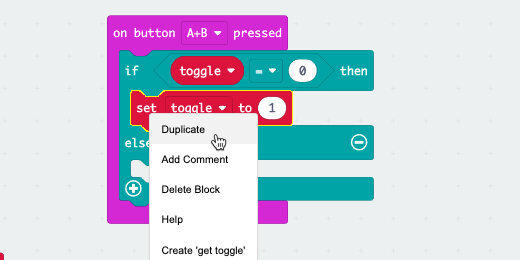
Place the duplicate code into the [forever] loop.

Remove the [set toggle to] code blocks.

Change the zero in the comparator to one.

Go to the Functions section; look for the call function block.

Place the [call comfortDisplay] code into the If section of the condition.

The condition compares the value of the [toggle] variable to the number. If the value of the toggle is one, then the display code is called to run. If the value of the toggle variable is NOT 1 then the function is not called. The Else part of the condition needs to be here even if we don't provide any code.
Go to the Variables section; get the [set toggle to] code block. Place it into the [on start] function. This sets the start-up value of the toggle variable to zero. The toggle is off and the comfort information will not display.

Run the program
The display on the Micro:bit is blank. None of the information received from the transmitting Micro:bit is displayed.

Click the A+B button.
The Micro:bit will display a sad face. The temperature will display a few seconds later.
The simulator is not receiving anything from the transmitter so it can only report a default value. That value is zero degrees Celsius or 32-degrees Fahrenheit.
Press the A+B button to turn off the comfort display.
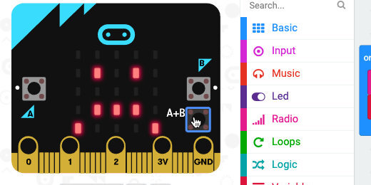
Press the A button to see the temperature in Celsius. Press the B button to display the temperature in Fahrenheit.
Ready to download
Download and transfer the Thermometer **Receiver** code to one Micro:bit.
Download and transfer the Thermometer **Transmitter** code to another Micro:bit.
Final notes
The transmitting Micro:bit does not display any content. There is no need to display anything since it is most likely to be out of sight. This extends the life of the battery if the sensor is going to be in a location for some time.
Micro:bit thermometer / thermostat
The Micro:bit has a sensor to measure the ambient temperature. It is not designed to be touching something like water. The sensor is inside the CPU.
The sensor is like a thermometer. A thermometer, like the one on the Micro:bit, can be used to trigger events. An event can include the update of information on a display or the activating of something like a cooler or heater.
When a thermometer is used to trigger events it is called a thermostat. Thermostats are usually used to regulate temperature. A thermostat does not have to be used to regulate temperature. It can be used for any number of actions in response to a temperature reading. For example, it could sound an alarm if the temperature is too low or high.
In the lesson, we are going to
1. Create code to display the ambient temperature in Celsius.
2. Update the code to display either Celsius or Fahrenheit.
3. Display a friendly icon when the temperature is in a comfort zone.
4. Display a sad icon when the temperature is in an uncomfortable zone
Project preview
A link to the completed project is available below. Use it to get a preview of the final product. The code is also available through my Github repository. Use the link to import the project.
Thermometer / Thermostat project from Make Code
Thermometer / Thermostat project from Github
Celsius and Fahrenheit
Two measurements are commonly used in everyday temperature measurements. Both use the freezing and boiling of water. Celsius uses 0 for the temperature at which water freezes. The boiling point of water is 100-degrees celsius. Fahrenheit uses 32 degrees for the freezing point of water and 212-degrees for the boiling point of water.
Fahrenheit uses zero-degrees to mark the point where an equal mixture of ice, water, and salt freezes. Salt in ice water causes the ice to release energy and make the water colder. This is how ice cream makers get super cold turn cream into ice cream.
The measurement interval between Fahrenheit and Celsius is different. The interval between the scales is five-ninths(5/9). This number is important when we are looking to convert one unit of measure to another. We will revisit this later.
The Micro:bit uses Celsius as the unit of measure for temperature.
Micro:bit simulator
You don’t need to have a Micro:bit to learn about the Micro:bit. Microsoft provides a free online Micro:bit simulator. No login account is required. Use the link below to access the simulator.
The simulator is also the environment we use to create code for the Micro:bit.
Create the project
Click the New Project button.

Set the name of the project to “Thermometer Thermostat”; click the Create button.

Each new project includes two code blocks. The [on start] code runs instructions the moment the Micro:bit powers up or is restarted. The [forever] loop runs code in the loop for as long as the Micro:bit is powered.

Sensor reading
We are going to display the reading from the temperature sensor.
Select the Basic code section; look for the [show number] code block.

Place the code block inside the [forever] loop.

Select the Input section.

Find the [temperature] code block.

Place the code block inside the [show number] parameter.

The simulator is not connected to a real sensor to take temperature measurements. The simulator provides a temperature slider to simulate the temperature received by the sensor. The temperature slider is set at the midpoint of 21-degrees Celsius.

Click and drag the slider to the top. The maximum temperature scale is 50-degrees Celsius.

Move the slider down. The lowest temperature registered by the sensor is -5-degrees Celsius.
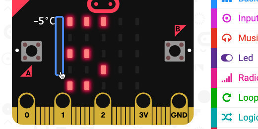
Fahrenheit
You probably want to know what the temperature readings are in Fahrenheit. We need to convert Celsius to Fahrenheit.
We aren’t just going to convert the temperature and forget about Celsius. We are going to use the Micro:bit buttons to provide the temperature information in Celsius or Fahrenheit.
Select the Input code section; get the [on button A pressed] code block.

Place the code block on the coding canvas.

Get the [show number] code from the [forever] loop and place it in the [on button A pressed] function.
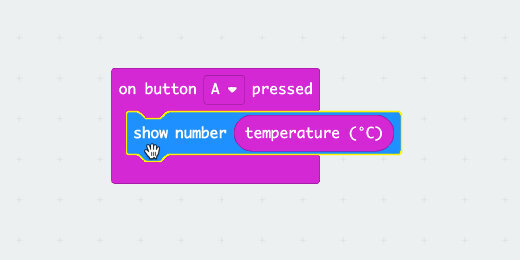
Press the A-button on the simulator. The temperature is sensed and displayed when the button is pressed.

We are going to do the same thing for button B. Right-click the [on button A pressed] code and select the duplicate option.

A copy of the code blocks is created and placed on the canvas. The code is a light green with hash marks. This indicates that the code is not active. Make Code does not permit two functions to be on the canvas for the same button.

Click the button selector; choose B.

When button B is pressed, the Micro:bit will convert Celsius to Fahrenheit.
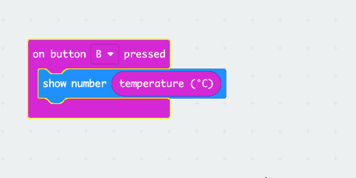
Remove the [celsius] input from the [show number] parameter. Set it to one side.

The difference in units of measure between Fahrenheit and Celsius is 5/9. The difference for the freezing point of water is 32. To convert Fahrenheit to Celsius we subtract 32. We then multiply that answer by 5/9. The formula is shown below.
Celsius = (Fahrenheit - 32) x 5/9
To convert Celsius to Fahrenheit we multiply 9/5, the inverse of 5/9, and add 32. We can use the conversation formula with a fraction, 9/5, or with a decimal. The fraction 9/5 is 1.8. The formula is shown below.
Fahrenheit = (Celsius x 9/5) + 32
Go to the Math code section. Find the multiplication operation.
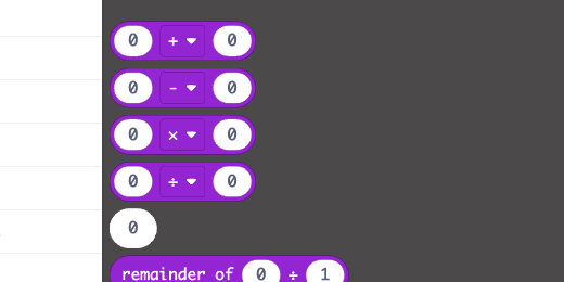
Place the operation code block inside the [show number] parameter.

Place the [temperature] code block into the left side of the multiplication operation parameter.

Enter 1.8 into the right side.

Return to the Math section and get the Addition operation. Place it on the canvas below the code we are working on. We are placing the code here for a moment so we can insert the multiplication operation into the left side of the addition operation.

Select the Multiplication operation and place it on the left side of the Addition operation. Make sure to select the operation block.

Select the math operation block and place it inside the [show number] parameter.

Enter 32 into the right side of the Addition operation.
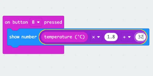
Go to the simulator and press the B-button. The slider shows the temperature in Celsius. The number scrolling across the display is the same temperature in Fahrenheit.
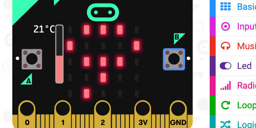
Move the temperature slider up and down. The maximum temperature in Fahrenheit is 122-degrees. The lowest temperature is 23-degrees.
Comfort zone
We are building on the same project to display a room temperature comfort meter. The Micro:bit will monitor the ambient temperature and report the comfort level. It will report this with icons and occasional information.
The comfortable temperature for most people ranges between 18 and 24-degrees Celsius, 64 and 75-degrees Fahrenheit. Temperatures above and below this range are uncomfortable. The thermostat will display a smiling icon when the temperature is within the range. It will display a Sad icon when it’s too cold and an Angry icon when it’s too hot.
Variables
We have an equation that converts Celsius to Fahrenheit. We need to use this conversion in at least one more location. This is reason enough to use variables.
Variables allow us to store values or the result of complex operations into a container. This container is used where needed without the need to enter the value or recreate the operation. They reduce the chances that we will make mistakes and increase the efficiency of programming.
Go to the Variables section; click the Make a Variable button.

Use “Fahrenheit” for the variable name; click the OK button.

Every variable gets three code blocks. Get the [set Fahrenheit to] code block and place it on the canvas.
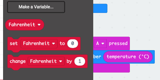
Get the conversation formula and place it into the [set variable] parameter.

Place the Set code block into the [on button B pressed] function; place it before the [show number] code.

Return to the Variables section and get the Fahrenheit variable block.

Place the variable into the [show number] parameter.

Right-click on the Set Variable code block; select duplicate.

Place the code inside the [forever] loop.
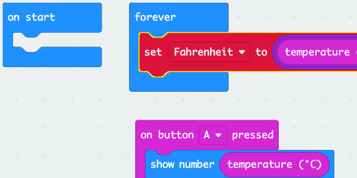
We need a variable for Celsius. We don’t need to convert to Celsius, but it is a good idea to keep things consistent and use variables when we might need to use a value more than once.
1. Return to the Variables section.
2. Create a new variable and use Celsius for the variable name.
3. Place the [set Celsius to] code block on the coding canvas.
4. Place the Celsius code into the variable parameter.
5. (You can either duplicate the code block or get one from the Input section)
6. Place the code into the [on button A pressed] function; above the [show number] code.

Move the button code blocks down and out of the way. We won’t be working on them until later.
Fahrenheit or Celsius
The choice to use Celsius or Fahrenheit is yours. I will use Fahrenheit. The same code works regardless of your choice.
We want to display a smiling icon if the ambient temperature is within the comfortable range, 64 to 75. To do this, we need a condition statement. A condition statement evaluates if something is True or False. The condition statement then performs an action based on the evaluation.
Go to the Logic code section. Look for the [if True then] code block.

Place the code block into the [forever] loop and below the Set Variable code.

If the temperature is below 64-degrees Fahrenheit, 18-degrees Celsius, we want to display a sad face icon. We need to compare the sensor reading to this value. To do that we need a comparator operator.
Go to the Logic section; find the Less Than comparator.

Place the comparator into the condition statement parameter.

Go to the Variables section. Get the variable for your measurement and place it on the left side of the comparator parameter.

Enter 64 into the right side of the parameter; enter 18 if you are using Celsius.

Go to the Basic section. Get the [show icon] code; place it inside the condition statement.

Change the icon to a sad face.

Right-click on the conditions statement; select duplicate.

Place the condition statement after the first.

Click the comparator selector; choose the Greater Than option.

Replace 64 with 75; use 24 for Celsius.

Change the sad icon to an angry icon.

These are the easy conditions. The one for the comfort zone is a little more involved. The condition statement needs to verify specific conditions are met. The lowest temperature must be greater than or equal to 64. The opposite of the first condition. The condition includes the requirement that the temperature is the SAME or greater. The other part of the condition is that the upper temperature is less than or equal to 75.
Boolean logic
Boolean logic is a form of algebra. It is built around three words known as Boolean Operators. The words are “Or”, “And”, and “Not”.
The “OR” operator requires one condition or the other to be Tue. The conditions in an “OR” can be of any number. It Does not matter which one is True.
The “AND” operator requires that all the conditions be True. It does not matter how many conditions there are; they all have to be True.
The “NOT” operator is used in conditions to exclude a condition. We can exclude one or more conditions.
Comfortable condition
The comfortable range is between 24 and 75-degrees. The temperature must be within this range. It cannot be just greater-than-or-equal-to 24. It must also be less-than-or-equal-to 75. This requires that both conditions be met, so we need to use the “AND” Boolean Operator.
Go to the Logic section and get a new [if True then] code block. Put the code on the canvas and to one side of the [forever] loop.

Return to the Logic section. Look for the “AND” operator in the Boolean section.

Place the operator into the condition statement parameter.

Go back to the Logic section. Get a less-than operator and place it on the left side of the Boolean Operator. Get another less-than operator and place it on the right side.

Change the less-than operator on the left to greater-than-or-equal-to. Chang the operator on the right to less-than-or-equal-to.

Get the condition statement and insert it between the other two conditions. It can go anywhere. I think this brings home the visual that the comfort level is between the cold and hot extremes.

Get a [show icon] code block and place it inside the condition statement. Use a Happy face for the icon.

Get the temperature variable and place it into the left side of the greater-than-or-equal-to comparator.

Get another temperature variable. Place it on the left side of the other comparator.

Enter 64 for the left comparator and 75 for the right comparator.

Test the code
Look at the simulator. The Happy icon is displaying. Move the temperature slider up and down to watch the icons update.

Move the slider and press the A or B button to display the temperature in either Celsius or Fahrenheit.
Display temperature
It would be nice to periodically display the temperature without having to press one of the buttons.
Go to the Basic section; find the [pause] code. It is near the bottom.

Place the code after the last condition.

Click the interval selector; choose 5-seconds.

Place the [show number] code block after the [pause]. Place the temperature variable into the parameter.

Clear the display
Everything is working nicely. The icon is followed by the temperature after a 5-second delay. The temperature information displays right next to the icon. This can make it difficult to read.
Go to the Basic section; find the [clear screen] code block. Place the code after the [pause].
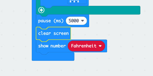
Conclusion
We have a thermometer that displays the temperature in Celsius or Fahrenheit with the press of a button. The thermometer causes an event to happen while constantly sensing the ambient temperature. We get different icons for different ranges of temperatures. We have a basic thermostat.
Micro:bit light meter for projects
The goal of the project is to create a light meter to register light values from two different sources at a time. The meter allows us to quantify the brightness of a source. These sources can include a candle, flashlight, LED, incandescent bulb, and fluorescent lights.

Micro:bit light meter
In this lesson, we are using the Micro:bit light sensor to record the light values of different sources. This makes for a nice science project.
The project
The goal of the project is to create a light meter to register light values from two different sources at a time. The meter allows us to quantify the brightness of a source. These sources can include a candle, flashlight, LED, incandescent bulb, and fluorescent lights.
Sources are not limited to objects. Sources can include locations like a classroom, the outside, a library, or a cafeteria.
I have provided Google Documents with tables of several objects and location ideas. Use the link below to get a copy of the Google Docs. Each document includes instructions.
Light meter comparison table for objects
Light meter comparison table for locations
Light meter comparison table for compare and contrast
You don't need to collect data with tables. The project will allow you to collect two separate light value readings and compare the different values with the Micro:bit.
Get the completed project using one of the links below.
Light meter project (Made Code)
Light meter project (Github)
Code outline
In the code, we are going to…
1. Activate the simulator light sensor.
2. Create code to store the value for one light measurement.
3. Create code to store the value for separate light measurements.
4. Create code to compare the two values.
Micro:bit simulator
You don’t need to have a Micro:bit to learn about the Micro:bit. Microsoft provides a free online Micro:bit simulator. No login account is required. Use the link below to access the simulator.
The simulator is also the environment we use to create code for the Micro:bit.
Create the project
Click the New Project button.

Set the name of the project to “Light meter”; click the Create button.

Each new project includes two code blocks. The [on start] code runs instructions the moment the Micro:bit powers up or is restarted. The [forever] loop runs code in the loop for as long as the Micro:bit is powered.
Simulated light
The simulator in Make Code cannot register the light through a sensor. It does; however, have a way to simulate the light received by the sensor. We will activate the simulated sensor to test the code during development. In the end, we will remove the code before downloading it to your Micro:bit.
Go to the Basic code blocks section and find the [show number] code block.
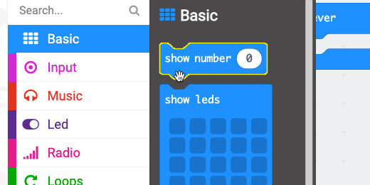
Place the code into the [on start] code block.

Go to the Input section. Find the [light level] code.

Pace the code into the [show number] parameter.

The simulator has a light meter tool in the top left corner.

We are going to store the value of one light reading into a variable. The value will be written to the variable when the A-button is pressed.
The first light value
Go to the Input section and find the [on button A pressed] code.

Place the code block on the canvas.

Go to the Variables section and click the “Make a Variable” button.

Use “1st light value” for the variable name; click the OK button.

We need another variable for the second light value. Make another variable. Use “2nd light value” for the variable name.
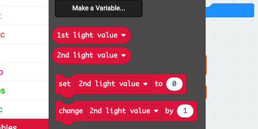
Get the [set variable value to] code block. Place it in the [on button A pressed] code function.

Click the variable selector and choose the “1st light value” variable.

Place the [light level] code, from the Input section, into the variable parameter.
This instruction activates the light sensor and records the reading into the variable “1st light value”.

Right-click on the [show number] code block in the [on start] function; select duplicate.

Place the duplicate code into the [on button A pressed] code block and after the [set variable to light level] code. This provides feedback for the value recorded into the variable.
The Micro:bit does not have a light meter like the simulator. We need a way to display the value recorded by the light sensor.

At this point, this is all we need to collect the light measurement from different objects or locations. You can download this code to the Micro:bit and use it as is. But, we are not done yet.
The second light value
The code to get the second light value is almost identical. We record the data into a separate variable and use a different button to start the process.
Right-click the [on button A pressed] code and select duplicate.

Place the code to one side. The code colors are dimmed in a hashed green. This is Make Code’s way of telling us that the code is not enabled to work. We cannot have two [On Button pressed] code blocks for the same button.

Click the button selector; choose the B-button.

Click the variable selector and choose the “2nd light value” variable.

Comparing measurements
Button A will record and store one light value. Button B will record and store another light value.
In the next part, we are going to write code to compare the values and show the difference.
To display the information we need to assign the instructions to a separate button or input option. There isn’t a third button option but there is the option to press both buttons at the same time.
Get the [on button A pressed] code from the Input section and place it on the coding canvas.

Select the A+B option from the button input selector.
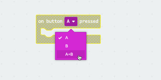
Get the [show number] code and place it in the [on button A+B pressed] function.

Go to the Math section; find the Subtraction operation. Place the code into the [show number] parameter.

Go to the Variable section. Place the [1st light value] variable into the left side of the operation. Place the [2nd light value] into the right side of the operation.

This is all we need.
Test the code
Go to the simulator and move the light meter to a value. Press the A button to record the reading. Move the light meter to a different value; press the B button. Press both A and B buttons to display the difference between the values.
One more thing
To make the displayed answer a little more friendly, I think we should have it display the numbers being subtracted in addition to the answer.
Get the [show string] code block from the Basic section. Place the code before the [show number] code.

Click the Advanced section option; find the Text code section.

Find the [join] code block.

Place the [join] code into the [show string] parameter.

Get the [1st light value] variable; place it into the first join parameter.

Replace the word in the second parameter with the minus symbol.

Click the Plus button in the [join] code to add another text parameter.

Place the [2nd light value] variable into the new text parameter.

Add another text parameter and type the Equal symbol into the parameter.

Run the program again. Get a new value for each of the variables and press the A and B buttons. The Micro:bit displays an expression of the light values and difference.
Cleanup
You don’t need the [show number] code in the [on start] function for the real Micro:bit. If you are going to download this to the Micro:bit. Remove the code.
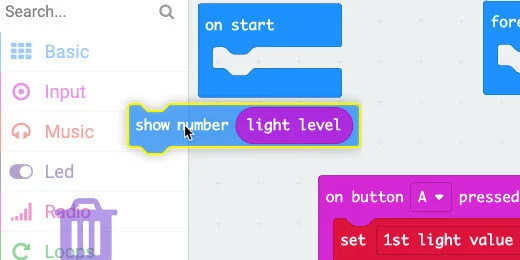
Micro:bit smart LED dimmer
Sensors on the Micro:bit and a little programming allow us to develop products that respond to input from the world in ways that produce desirable results.
Light sensors are used in a variety of real-world applications. Light sensors are used in outdoor lights to turn them on when it gets dark. The same sensors turn the lights off when the sun is out.

Smart light sensor dimmer
Sensors on the Micro:bit and a little programming allow us to develop products that respond to input from the world in ways that produce desirable results.
Light sensors are used in a variety of real-world applications. Light sensors are used in outdoor lights to turn them on when it gets dark. The same sensors turn the lights off when the sun is out.
Sensors and programming help create sophisticated applications.
The light sensor on the Micro:bit can be used to gradually make adjustments based on the ambient light. I covered this in the light sensor basics with a simple application.
Use the link below to see the light sensor introduction lesson.
Turning lights on or off when the ambient light changes is a basic smart switch. In the introductory lesson, we adjusted the LED brightness using the ambient light to control the brightness. As the ambient light rose, the LED lights got brighter. This isn't very useful because we don't need the LEDs to get brighter as the ambient light gets brighter. We need the opposite to occur.
Project objective
This project integrates some basic math along with process skills. The project aims to create a responsive sensor like that used in modern cars.
The display in modern cars decreases the panel lighting to compensate for the brightness of the daylight hours. The display gradually increases as the sun goes down. The brightness is not increased too much. Just to a comfortable level. This setting is often adjustable by the driver or passenger.
The project uses the light sensor to gradually decrease the LED luminance as the ambient light gets brighter. The Micro:bit will also gradually increase the luminance as the ambient light gets dimmer.
Use the link below to get a copy of the final product.
Smart LED dimmer (Make Block Micro:bit)
Smart LED dimmer (Github)
Development
You don’t need to have a Micro:bit to learn about the Micro:bit. Microsoft provides a free online Micro:bit simulator. No login account is required. Use the link below to access the simulator.
The simulator is also the environment we use to create code for the Micro:bit.
Download the completed project using the link below.
Click the New Project button.

Set the name of the project to “Responsive LEDs”; click the Create button.
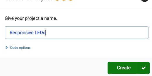
Each new project includes two code blocks. The [on start] code runs instructions the moment the Micro:bit powers up or is restarted. The [forever] loop runs code in the loop for as long as the Micro:bit is powered.
We need something to look at when adjusting the display brightness. Go to the Basic code section; look for the [show icon] code block.

Place the code block inside the [forever] loop.

We want the responsive light meter to begin with standard light measurement. That standard measurement for this project will be the midpoint for the light sensor.
Go to the Basics code section; find the [show number] code block.

Place the code block in the loop and below the icon code block.

Go to the Input code section and find the [light level] code block.

Place the code block into the [show number] parameter.

This code block displays the sensor reading from the Micro:bit. Look at the Micro:bit simulator. There is a brightness simulator icon in the top left corner. The simulator is also a meter for the amount of light that is being received by the sensor. The simulator shows that that the sensor is sensing about half the light it can register. This reading is in the simulator. The physical Micro:bit uses an estimate of the ambient light.
The LEDs used to sense light are not as accurate as using a Light Dependent Resistor(LDR). This is an independent component dedicated to converting light into electrical signals. The Micro:bit uses some algorithms to get a fairly accurate representation of the ambient light strength.
The light sensor returns a range of values from 0 to 255 (0 is dark and 255 is bright). The reading of 128 is right in the middle.
This is a good value to use for comparison.
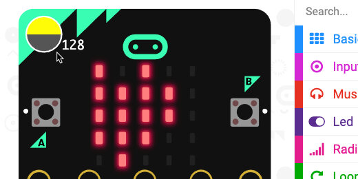
The Micro:bit needs to make decisions based on the base reading of 128 and the ambient light.
We are using conditional statements to make our decisions. Conditional statements include statements like “If something is True Then take this action”. The opposite of this statement is that “If something is False then take an action”. The action taken depends on what we want to do.
Go to the Logic section; look for the [If True Then] code block.

Place the condition statement inside the loop and below the [show number] code block.

The condition statement is looking for something True. We need to provide something to return a True or False response.
Look for the “Less Than” comparison code block in the Logic section.

Place the comparison code block into the condition statement parameter.

Go to the Input section and get the [light level] code block. Place the code on the left side of the comparator.

We want to compare the ambient light level to our base, 128. Type 128 into the right side of the comparator parameter.

The condition will compare the ambient light level to 128. If the light level is less than 128, then it will perform the instructions. We will get to that in a moment.
Variables
We typed 128 as the parameter into the comparator. In the future, we might want to change the base comparison to something else. Hard coding this value into the code is not a good idea if we intend to change the value in the future. Using a variable makes it easy to update the value for all the parameters in our program.
Go to the variables section and click the Make a Variable button.

Use “Base level” for the variable name: click the OK button.
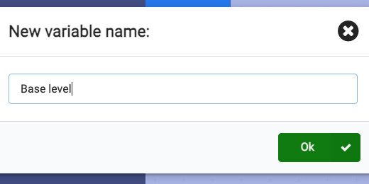
Get the [Base level] variable.
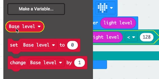
Place the variable into the right side of the comparator; in place of the value.
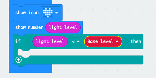
Go back to the Variables section; get the [set variable to] code block.

Place the code block inside the [on start] code; set the value to 128.

When the ambient light increase or decreases, we want the light to increase or decrease proportionally. To do this, we need to get the difference between the ambient light and our base. We need to compensate for the difference and add the difference.
We need another variable to help with the math operations.
Go to the variables section and create another variable. Use “light” for the variable name.
Get the [set light to] variable block.

Place the block inside the condition statement.

We need to determine the difference between the base light and the ambient light. Go to the Math section. Get the subtraction code block and place it in the variable parameter.

Place the [Base level] variable into the left side of the operation.
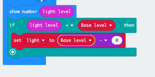
Get the [light level] input and place it on the right side of the operation.

This takes the base light level of 128 and subtracts the ambient light. For example, if the ambient light is 90, the difference is 128 - 90 or 38.
We want to increase the light level by this amount. The amount has to be increased beyond the 128 base value. We need to add the difference to the base to increase the light level.
Go to the LED section and the more subsection; find the [set brightness] code block.

Place the code block inside the condition statement and after the [set variable to] code block.

Place an addition operation code block from the math section into the [set brightness] parameter.

Get the [light] and [Base level] variables. Place the [light] code into the left side of the addition operation. Place the [Base level] code on the right side.

Let’s test the sensor. Adjust the lightness meter to any value less than 128.
It isn’t easy to tell if the LEDs are getting brighter in the simulator.

Sensor feedback
We need a way to verify that the program is working. The number scrolling across the display is that of the ambient light level. We need to display the LED brightness level instead.
Go to the LED section and the More subsection. Find the [brightness] code block.

Place the [brightness] code block into the [show number] parameter.
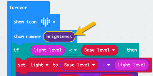
Return to the simulator and adjust the light meter. The meter in my simulator reads 112. The number scrolling across my display reads 144. The difference between 112 and 128 is 16. When we add 16 to 128 we get 144. The brightness of the LEDs has increased.

Dimming the LEDs
Reducing the brightness uses the same process. The math is slightly different.
Right-click on the condition statement; select duplicate.
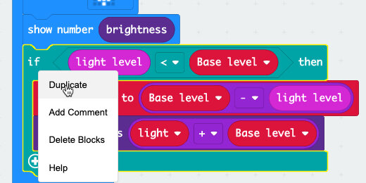
Place the duplicate condition statement below the first.

We need to see if the ambient light is greater than the base light. Change the less than symbol to greater than.

We need to subtract the base light from the light level. There are a couple of ways to do this next step.
Absolute values
The first option is to remove the [Base level] and [light level] code blocks from the [set variable to] code. Set them to one side.

Put the code blocks back. Place the [light level] into the left parameter and the [Base level] into the right parameter.

Here is another way to do the same thing. This is good when you get into studying absolute values. I put the code blocks back the way they were.
Get the [absolute of] code block from the Math section.

Place the block on the canvas outside the code.
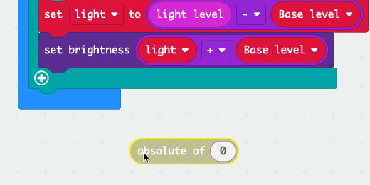
Move the mouse arrow over the subtraction operation. Make sure the operation is surrounded by a highlight.

Place the operation block into the [absolute of] parameter.

Place the [absolute of ] code block into the [set light to] parameter.

Now we need to set the brightness. We need to subtract the ambient light from the base light level. Switch the [light] variable and the [Base light] variables. Change the addition to subtraction.

Go to the simulator. Reduce the brightness level. Dim LEDs are easier to see in the simulator.

One more thing
We don’t need the feedback to display across the Micro:bit. Grab the [show number] code block and move it out of the loop. The attached code below is moved along with this one block. Put the code block back in place.

There is a better way to remove just one code block without having to juggle lots of code blocks around.
Hold the Option key on your keyboard while dragging the code block away. This isolates the one code block from the others.

Take the code block to the codes section.

The program is complete. Send the code to the Micro:bit if you have one.
Micro:bit light sensor basics
The Micro:bit has LEDs that emit light. The same LEDs are used to collect and measure light. The LEDs on the Micro:bit perform double duty.
In this lesson, we are going to:
1. Learn to measure the light received by the sensor.
2. Set the brightness of the Micro:bit LEDs based on the ambient light.
3. Turn the LEDs On or Off based on the ambient light.

Micro:bit light sensor
The Micro:bit has LEDs that emit light. The same LEDs are used to collect and measure light. The LEDs on the Micro:bit perform double duty.
In this lesson, we are going to:
1. Learn to measure the light received by the sensor.
2. Set the brightness of the Micro:bit LEDs based on the ambient light.
3. Turn the LEDs On or Off based on the ambient light.
You don’t need to have a Micro:bit to learn about the Micro:bit. Microsoft provides a free online Micro:bit simulator. No login account is required. Use the link below to access the simulator.
The simulator is also the environment we use to create code for the Micro:bit.
Use the link to go to the Make Code website. Click the New Project button.

Use “light sensor project” for the name and click the Create button.

Each new project includes two code blocks. The [on start] code runs instructions the moment the Micro:bit is turned on or restarted. The [forever] loop runs code in the loop for as long as the Micro:bit is powered.

A BIT of information
A bit is the smallest container of information. A bit holds a maximum of two values, either 1 or 0. These represent programmings states like yes, no, on, off, true or false. The states are translated into information. The combination of possible states is expressed as an exponent. Eight bits is 2 to the power of 8 or 256 bits of information. The number of bits here is exactly what the Micro:bit uses to represent the amount of light received by the sensors. The Micro:bit detects light with the LED sensors. The light is processed and the intensity of the light is converted to a number range. That range is 0 to 255.
Measuring light
Go to the Basic code blocks section. Find the [show information] code block.

Place the code block into the [forever] loop.

Go to the Input section; find the [light level] code block.

Place the code into the [show number] parameter.

Look over at the simulator. A simulated light meter is placed at the top left corner. The LEDs on the Micro:bit scroll to display the light reading. The light reading is also represented below the light meter. That reading is 128. This number represents the midpoint of the possible light received by the sensors.

Use the mouse arrow to change the light level. Click inside the meter and move the pointer up. This reduces the light intensity. I reduced the light intensity to 98 in my example. Drag the meter down to increase the light intensity.

Dimming
Let’s use the sensor as a dimmer. A dimmer reduces or increases the light based on sensor input.
Remove the [show number] block and set it to one side.

Go to the Basic section; get a [show icon] code block and place it in the loop.

Go to the LED section and into the More section. Find the [set brightness] code block.

Place the code into the loop and below the [show icon] code block.
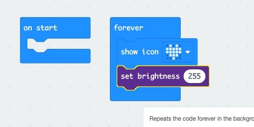
Get a [light level] code block from the Input section and place it into the [set brightness] parameter.

Go over to the simulator. Move the light input meter up and down. Watch the icon increase and decrease in brightness.

The brightness of the LEDs is proportional to the light level received from the sensor. The sensor provides graduated information to the program. The program uses this information to brighten or dim the LEDs accordingly.
On/Off sensor
The sensor can be used as a simple switch. We need to use conditions to decide when to turn the LEDs On or Off. We want the LEDs to turn on when the light level on the meter is below a certain value. We can choose any value.
Remove the [set brightness] block from the loop and set it to one side.

Go to the Logic section and find the [if True then] code block.
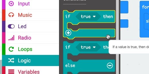
Place the condition statement inside the loop and below the [show icon] code.

The condition statement looks for a condition to be True.
We want the condition statement to look at the light level information. If the value from the meter is less than a certain value, we the LEDs to turn on. If the value is greater than a certain value we want to turn the LEDs Off. We can choose any value to trigger the switch.
We need a way to store this value and pass it into the condition and parameters later. The value will be stored in a Variable.
Go to the Variables section and click the "Make a Variable" button.

Set the name of the variable to “light trigger” and click the OK button.

Variable code blocks are created. Get the [set variable to…] code block.

Place the code block into the [on start] section. You might need to move the code blocks around.

Enter 100 into the variable parameter. This assigns 100 to the variable. The value is assigned when the Micro:bit turns on or is restarted.
This is our value to turn the LEDs On or Off.

Go to the Logic section and into the Comparison blocks. Look for the [less than] cod block.
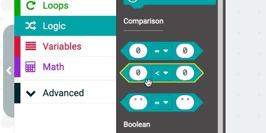
Place the code block into the condition parameter.

Get the [light trigger] variable and place it into the right side of the [less than] parameter.

Get the [light level] input and place it into the left side of the [less than] parameter.

Get the [set brightness] code block we set aside earlier and place it into the condition statement.
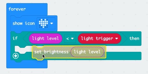
Remove the [light level] code from the [set brightness] parameter.

Take the code to the Codes section to remove it from the coding area.

If the light level is less than the light trigger, 100, we want the LEDs to turn On. The brightness value is already set at 255. This is the maximum brightness. This takes care of turning the LEDs On.

We need to follow the same process for turning the LEDs Off. The process is just reversed. The condition statement turns the LEDs Off when the light level is greater than the light trigger.
Right-click on the condition statement; select the duplicate option.
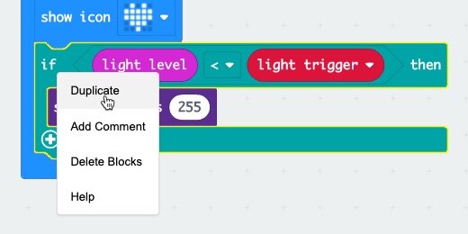
Place the duplicate below the first condition statement.

Click the comparator selector; choose the greater than comparator option.

Change the brightness level to 0.

Move the light sensor meter to a value less than 100; the icon lights to full brightness.

Move the meter to a value greater than 100; the icon turns off.

The light trigger might be too high or low. Change the value in the light trigger variable to 50 or 150. Choose a value of your own.

Micro:bit accelerometer Introduction
The Micro:bit has a variety of sensors. One of these sensors includes an accelerometer. The accelerometer is behind the B-button. A label on the Micro:bit behind the buttons points to the motion sensor.
The word accelerometer might make you think that it measures acceleration. The accelerometer measures motion. The motion comes from lifting or rotating the Micro:bit.
The accelerometer measures motion in three different directions. It measures motion when the Micro:bit is moved side to side or up and down.

Microbit accelerometer
The Micro:bit has a variety of sensors. One of these sensors includes an accelerometer. The accelerometer is behind the B-button. A label on the Micro:bit behind the buttons points to the motion sensor.
The word accelerometer might make you think that it measures acceleration. The accelerometer measures motion. The motion comes from lifting or rotating the Micro:bit.
The accelerometer measures motion in three different directions. It measures motion when the Micro:bit is moved side to side or up and down.
We need a frame of reference when we talk about the motion. Look at the Micro:bit with the contacts facing down. Use the image below as a reference. Place the Micro:bit on a flat surface.
Moving the Micro:bit from left to right is moving along the x-axis.

Moving the Micro:bit up and down is moving it along the y-axis.
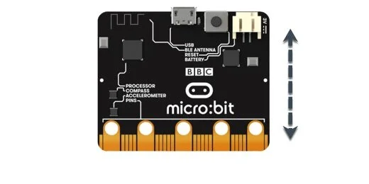
Lifting the Micro:bit from the surface is moving it along the z-axis.
The accelerometer measures motion. It measures motion in varying degrees from slight motion to extreme motion. The accelerometer also uses gravity to determine the direction of motion. Motion is not just from side to side or up and down. Rotating the Micro:bit is also considered motion. We are going to focus on rotating the Micro:bit in this lesson.
You don’t need to have a Micro:bit to learn about the Micro:bit. Microsoft provides a free online Micro:bit simulator. No login account is required. Use the link below to access the simulator.
The simulator is also the environment we use to create code for the Micro:bit.
Measuring motion
The best way to understand the motion sensor is to watch it in action.
Click the New Project button.

Use “accelerometer basics” for the project title; click the Create button.

The simulator places two code blocks on the canvas for every new project. The Start code runs code when the Micro:bit starts or is reset. The Forever code is a loop that repeats instructions for as long as the Micro:bit is powered.

We don’t need the [on start] code. Drag it to the code panel.

Select the Basic codes section.

Drag the [Show number] code block and insert it into the Forever loop.

Select the Input section.

Find the [acceleration] code block.

Place the acceleration code block into the [show number] parameter.

The [acceleration] code has three measurement options. Click the Axis selector. The other axis options include the y and z-axis. Leave the selector set to the x-axis.

The simulator shows a big fat zero. The Micro:bit is not moving in any direction. The simulator shows the value for the axis below the B-button.
This is not true in the actual physical Micro:bit.
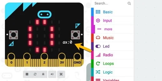
Move your mouse pointer over the Micro:bit simulator; place it over the right edge. The LEDs on the Micro:bit begin to scroll to display the value of the acceleration. The value is also displayed below the B-button. The extreme value and the largest value we can get is 1023.
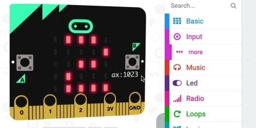
Move the mouse pointer to the left side of the Micro:bit. The measurement is -1023 at the extreme value.
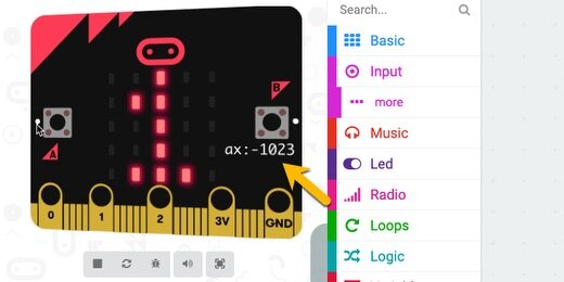
The value 1023 is the largest value we can get when measuring acceleration. This isn’t how fast the Micro:bit has moved. It measures the amount of movement from the center of the Micro:bit when it was laying flat.
Imagine the Micro:bit is laying flat. The image below is in a coordinate plane with x and y-axis lines.

Tilting the Micro:bit to the right increases the motion to the sensor. The measurements go up to a maximum of 1023.

Tilting the Micro:bit to the left increases the motion sensor. This time, the readings are in the negative range from 0 to -1023.

The numbers are represented with negative values because of the coordinate plane. Numbers on the left side of a coordinate plane are negative.
Return to the coding canvas. Select the y-axis in the acceleration code.

Place the mouse cursor over the top center of the Micro:bit. The y-axis value is -1023.

Move the arrow to the bottom center of the Micro:bit. The value is positive.

Move the cursor around the Micro:bit simulator. The numbers displayed range from 0 to 1023 depending on where you place the arrow.
X and Y-Axis measurements
We can get both x and y-axis measurements at the same time. Right-click the [show number] code and select the Duplicate option.

Place the duplicate below the original.
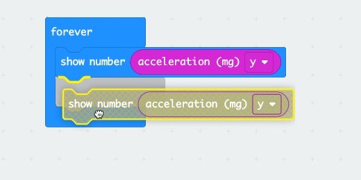
Change the axis of the first to the x-axis.
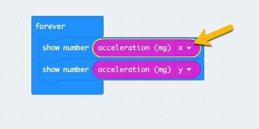
On the simulator, we see information for both the x and y-axis.

Place the mouse arrow over the right edge of the simulator. The Micro:bit displays one value for the x-axis and one for the y-axis.

Accelerometer and input
The accelerometer is an input device. It is also a sensor. It takes information from the surroundings and interprets that information for the Micro:bit to use. We use that interpreted information to react to the input.
Remove both [show number] blocks from the Forever loop.

Go to the LED section and find the [plot bar graph of…] code block.

Place the code block inside the Forever loop.

Go to the Input section and get an [acceleration] code block. Place it into the first parameter.

The bar graph code block creates a bar chart from the information passed into it by the acceleration code. The acceleration code receives information from the sensor. This information is in the form of numbers ranging from 0 to 1023.
The second parameter in the bar graph code block needs the maximum number we want to use in the bar graph. We can choose any number from 0 to 1023. Enter 1023 into the parameter.

Place the pointer over the center of the Micro:bit simulator. Move the arrow to the right, slowly. A bar chart will gradually form and eventually fill the Micro:bit.

Move the pointer to the left side of the Micro:bit. The same chart is created. The chart is created even if the values are negative. The Micro:bit is taking the absolute value of the reading and creating the chart. The absolute value for the readings is positive.

Making decisions
Computers don't think and reason on their own. We can help them make decisions based on the parameters we choose. We will use a condition statement to prevent the Micro:bit from creating a chart when the values are negative.
Go to the Logic section and find the [if True then] code block.

Place the condition code block inside the loop.

Move the [plot bar graph] code block inside the condition block.

The condition statement checks to see if a statement is True or False. The parameter is set to look for a True statement. We need to provide the statement to verify.
Go to the Logic section and find the Comparison operators.

Place the [Less than] comparison operator into the condition parameter.

Click the comparison selector and choose the “Greater Than” option.

Right-click the [acceleration] code and select duplicate.

Place the [acceleration] code into the left parameter of the comparator.

The code explained
The condition compares the value from the accelerator to the number in the right parameter. If the value from the accelerometer is greater than zero, True, then it will run the code in the condition. It will plot the bar graph. If the value is “Less Than” zero, False, then the Micro:bit will not plot the graph. False in this sense means that the value from the accelerometer is not greater than zero.
Test the code
Rotate the Micro:bit to the right; it will plot a bar graph.
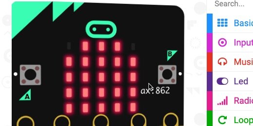
Rotate the Micro:bit to the left; it will NOT plot a bar graph.

Acceleration to control Input
The bar graph is plotted as we rotate the Micro:bit. If you rotate the Micro:bit slowly, you will see the graph plotted gradually. We can use the same principle to control almost any input to a program.
The following code uses the [acceleration] code information to control the brightness of the LEDs on the Micro:bit.
Remove the Condition code with the graph plot from the Loop. Set it to one side.

Go to the Basic code section. Get the [show icon] code block and place it into the loop.

Go to the Led section and into the More option. Find the [set brightness] code block.

Connect the [set brightness] code block to the [show icon] code.

Get an [acceleration] code block and place it into the [set brightness] parameter.

Rotate the Micro:bit gradually to the right. The LEDs will get brighter as the number increases. Rotate it to the left and the LEDs will dim. The LEDs do not get bright again if we rotate the Micro:bit to the far left. The brightness code block already understands we can’t brighten something with negative values.