Micro:bit conductivity tester

Conductivity tester
There are items everywhere that conduct electricity. They allow electrons to flow from one end of a circuit to another. Some items are better at conducting electricity than others. Items that resist the flow of electricity are called resistors. Some items prevent the flow of electronics completely. These are known as insulators.
Conductors and resistors are very similar. Both of them allow electrons to flow through a circuit. Resistors allow less of the electrons to flow. Some electronic components need more current and some require less. Too much current going to a component that requires less can damage the component. Resistors are used to reduce the amount of current going into those components.
The conductivity tester in our lesson will help us identify items that are conductors, resistors, or insulators.
I have created a table with items to test for conductivity and resistance. The table contains items that are solids and others that are liquids. I tried to keep the list to items that are inexpensive and easy to gather. Feel free to modify the table of items to suit the needs of your classroom.
I included items with liquids to demonstrate that not all conductors are solids. This is one reason we don’t touch circuits with wet hands. Liquids with impurities facilitate the flow of electrons.
Use this lesson for a basic introduction to conductors, resistors, and insulators. The tables include spaces for values. You might want to graph these values in your activities.
Supplies
1 Micro:bit
1 Micro:bit power supply (battery pack or computer)
2 alligator clip connectors
2 medium or large paper clips
materials to test
Resources
Use the links below to get a copy of the final project.
Basic conductivity worksheets
Extended conductivity activity
conductivity tester Make Code :
https://makecode.microbit.org/_9gDPbzK8p2Xg
conductivity tester Github :
https://github.com/digitalmaestro/conductivitytester
Conductivity tester
We are using the Make Code development environment from Microsoft. We don’t need an account to create projects with Make Code. Use the link below to access the Make Code development environment.
Click the New Project button.

Use ‘conductivityTester’ for the project name; click the Create button.

Every new project includes two code blocks on the coding workspace. These blocks include the [on start] section and [forever] loop.

The [on start] section is used to run code as soon as the Micro:bit starts or is restarted. This is where we usually define variables.
The [forever] loop runs code for as long as the Micro:bit is powered. Code inside this loop does not require any user interaction. This is where we will develop the code for our tester.
The Make Code development environment has a Micro:bit simulator. The simulator has contacts along the bottom, just like the real Micro:bit. Some of the contacts have labels. Contacts with labels 0, 1, and 2 are used for external components. The contact labeled 3V provides 3-volts to external components. The GND contact is called the Ground. All circuits need to be connected to a ground to complete the circuit. Think of the ground as the negative side of a battery terminal.
Important: Never connect the 3v and GND directly. This could severely damage your Micro:bit.
The contacts labeled 0, 1, and 2 are referred to as General Purpose Input and Output pins. They can function as either input or output. We will use one as an input.
We are going to use the simulator to provide a foundation for the readings from the actual Micro:bit. This will help us understand the information to be displayed later.

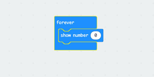
Go to the Basic code section; find the [show number] code block.
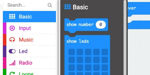
Place the code block into the [forever] loop.
Select the Advanced section to display more code block options.

Select the Pins section.

Find the [analog read pin] code block.

Place the code block into the [show number] parameter.
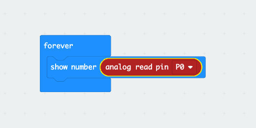
This code displays the information read by one of the contacts. The contact in this example is contact zero.
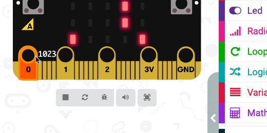
The simulator has a small number—zero—to the right of contact. This number provides feedback on simulated input. This number does not appear on the real Micro:bit. It is here to simulate input for the contact. The Micro:bit displays the number zero too.

Click on the contact and drag it up. You're going to see a color bar rise as we move the mouse pointer up. The value next to the contact will increase too. This number represents electric current. The current is combing from the Micro:bit voltage supply.
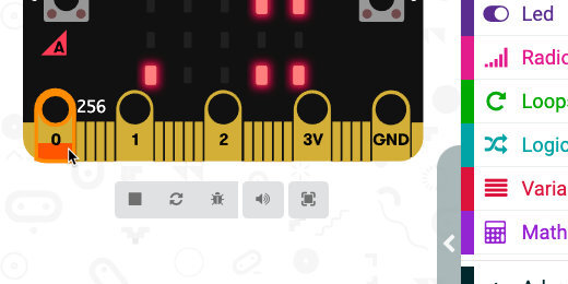
Drag the meter to the top of the contact. Stick to the edges of the contact to go around the circle or whole in the Micro:bit. The maximum value for the input is 1023.
What does the number mean?
The value of 1023 comes from Micro:bit's use of the 10-digit binary system. Every bit of information in a computer is either 1 or 0. Bits are combined to create everything in the computer. Characters are often stored in 8 or 10-bit binary strings. A string of 8 bits can represent 256 values. That number is 2 raised to the power of 8. A string of 10 bits can represent 1024 values. Increasing the number of bits provides more values and greater precision.
The Math is Fun website provides a nice explanation of the binary system. Use the link below to access the binary page for more information.
https://www.mathsisfun.com/binary-number-system.html
Variables
We need a variable to store the information read by the input pin. Go to the Variables section; click the ‘Make a Variable’ button.

Use ‘current’ for the variable name; click the OK button.

Three blocks are created for each variable. The first block is the variable itself. The Set block is used to assign values to the variable. The values can be numbers, letters, or operations. The Change code block is used to change variables with numbers using some regular amount.

Get the [set current to] code block; Place it into the [forever] loop. Place it above the [show number] code block.

Get the [analog read pin] from the [show number] parameter; place it into the [set current to] parameter. This code assigns the value read from Pin0 to the variable [current].

We don’t need the [show number] code. Right-click on the code block; select the Delete block option.

If an object is conductive, it will permit a flow of current. Any amount of current will be good enough for us to determine if an item is a conductor. The lowest value recorded by the micro:bit is zero. When it displays zero, no current is flowing through the Micro:bit. When a value is greater than zero means that some current is flowing. We will see later that this is not so for the physical Micro:bit.
Go to the Logic section; find the [if…then…else] condition code block.

Place the condition code block in the loop, after the variable.

The condition statement needs to evaluate a condition. It needs to evaluate if something is True. Go back to the Logic section; find the less-than comparison code block.

Place the Comparison code block into the condition evaluation parameter.

Click the comparison selector; choose greater-than.

Go to the Variables section. Get the [current] variable; place it on the left side of the comparison code.

If the value in the variable [current] is greater than zero then we want to display something.
Go to the Basic section; find the [show icon] code block.
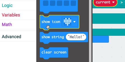
Place the code block into the first section of the condition statement.

Click the icon selector; choose the checkmark icon or any icon you prefer.

Go back to the Basic code section. Get another [show icon] code block; place it in the Else section. Change the icon to an ‘X’ or any icon you prefer.

The Micro:bit will display an X as long as the probes are not connected to an object that conducts electric current. A checkmark will appear once the probes come into contact with something that conducts electricity.
Simulation vs reality
The simulator shows that the Micro:bit returns a value of zero when it is not connected to a conductive object. This is not so for the physical Micro:bit. This is not what I expected when I downloaded the program to the Micro:bit.
When coding we often run up against things we didn’t expect. Dealing with those unexpected situations is a big part of coding. We need to calibrate the values in our code before using it to test for conductivity.
If you were watching NASA and Ingenuity, you know that unexpected things happen. The NASA programmers had to upload a fix to the program before Ingenuity could fly.
Go to the Basic code section.
Get the [show number] code block; place it after the set code.
Place the [current] variable into the [show number] parameter.
Place a Pause code block after the [show number] code.
Change the pause duration to 500(ms).
Add a [clear screen] code block after the pause code.

Click the Actions menu and select Download to micro:bit.

Don’t touch any of the contacts on the Micro:bit. The Micro:bit will display the checkmark followed by a number value. This is the pin reading from the Micro:bit. The number displayed on my Micro:bit is 208. The number displayed on yours might be different.
I went through the same process on three other Micro:bit. Each one gave me a slightly different number. The number displayed is the value at which nothing is connected to any of the contacts.
Calculate voltage
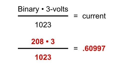
This value represents the current or volts registered by the Micro:bit. We can determine the voltage with a simple math formula. The formula is in the image below.
The total value we can get from the reading is 1023. The voltage from the Micro:bit is 3-volts. Multiply the reading from the Micro:bit, 208 in my example, by 3-volts. Divide the product by 1023. The answer for my example is .60997 volts. This is less than one volt.
We can come to an agreement that any reading that is less than 1-volt can be ignored. This eliminates the strange readings which are probably caused by static electricity and electronic devices surrounding the Micro:bit.
The binary number 1023 represents a total of 3-volts. Dividing 1023 by 3 will give us the binary equivalent of 1-volt. Return to the code; enter 341 into the comparison parameter.

Download the updated program to the Micro:bit. The Micro:bit will display the binary value from the contact reading. Use this value to calculate the voltage going through the conductor.
Connections and examples
Connect the alligator clips to the 3-volt and Pin-0 connectors.

Connect the Micro:bit to a power supply.

Don't dip the alligator clip into liquids. Don't pierce the fruit and vegetables with the clip either. Use a probe; I like paper clips.
*Don’t drink the liquids after testing!*
*Don’t eat the fruit after testing!*

Use the curled inside of the paperclip to grip the sides of containers. Glass and plastic are good insulators. Use glass or plastic to hold the liquids for testing.
