Change the brightness of an LED with TINKERCAD and Arduino

Introduction
In a previous article, I posted a lesson for using TinkerCad to construct a basic LED circuit. The LED in the circuit is turned on or off using an Arduino and a few lines of code. We used code to instruct Arduino when to turn the LED on or off. That’s as far as we got in that lesson. The link to the lesson is below.
https://digitalmaestro.org/articles/electric-circuits-and-arduino-with-tinkercad
In this lesson, I want to take the same instruction one more step. In the previous lesson, the LED was either on or off. We had no way of adjusting the brightness. We are going to address that option in this lesson. The link to the completed project is available below.
https://www.tinkercad.com/things/iOxi8dvvqMP
For this lesson, you need a TinkerCad account. The account is free. Go to tinkercad.com if you don’t have one.
New Circuit
Go over to tinkercad.com and log in. Click the circuits button. The button is in the menu on the left. Click the create new circuit button.

Click the random name assigned to the project. Change the name to variable led brightness.

Find the small breadboard in the components panel. Drag it onto the canvas.
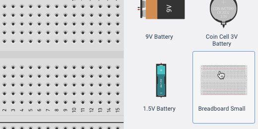
Find the LED component.

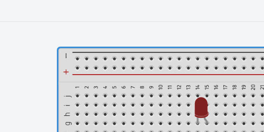
Place the LED on the breadboard. Place it somewhere in the middle. Leave space to attach wires above and below the connectors.

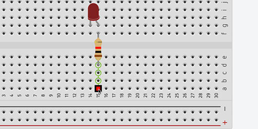
Find the resistor in the components panel.

Place the resistor across the upper and lower halves of the breadboard. Align the resistor with the Anode of the LED. The Anode is represented by the bent connector.

Click on a hole across from the resistor. This activates the wire tool and begins a wire connection.
Click a hole in the positive side of the terminal rails. Press the ESC key on your keyboard to release the wire tool.

Click the wire color selector and choose red.

This connects the resistor and LED to the positive terminal.

Connect a wire from the Cathode on the LED to a negative connection on the terminal. Set the wire color, choose black.

Click somewhere along the edge of the breadboard. This selects the breadboard. We need to reduce the size of the breadboard to make room for the Arduino.
TinkerCAD does not have many menu options. We need to use shortcut keys to manipulate some objects. Use the Alt and the minus(-) key on Windows and Chromebook. Mac users, use the Command and the minus(-) key. Use the Alt or Command key in combination with the plus(+) key to increase the size.

Click and drag the border of the breadboard toward the top of the canvas.
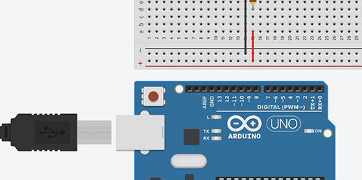
The Arduino is just below the breadboard in the components panel.

Place the Arduino below the breadboard on the canvas.
Connect a wire from the Arduino GND GPIO to the negative side of the terminal rail. GPIO stands for General Purpose Input/Output.

Arduino has several types of GPIO connections. The side of the board we are looking at as numbers from zero to thirteen. GPIO pins 0 and 1 are for transmitting text messages. Pins 2 to 13 are used for components.
Some of the numbers have a squiggly line. This is the Tilde character. Numbers without the tilde represent digital pins. We use these pins to turn the LED On or Off. Digital pins provide On or Off options only. These pins provide either zero volts or 5 volts.
Pins with the tilde character provide Pulse Width Modulation. These pins provide varying voltages.
Connect a wire from pin 6 to the positive terminal.

Coding Arduino
Click the code button to reveal the coding panel.
The panel has some code to get us started. This code is used for the built-in LED.

We don’t need this code. Drag the code blocks to the code section.
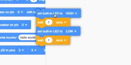
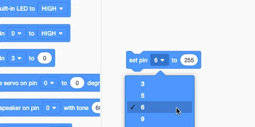
There are two set pin code blocks. One is used with the digital input pins. It has two parameters, high or low. The other set pin code block has a variable parameter. Drag this code block onto the coding area. This is the only code block we need.

Change the PIN number to 6. Change the variable to 255.
Click the Start Simulation button.

The LED should be on.

Click the Stop Simulation button.

Change the variable to 128. Start the simulation.

The available numbers for the variable range from 0 to 255. The total is 256. The value of 128 represents half of 256. The LED will light with half the illumination.
It is hard to tell but the LED is shining with half the brightness.

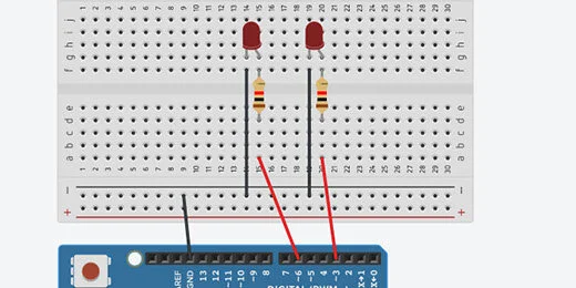
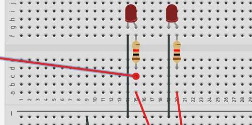
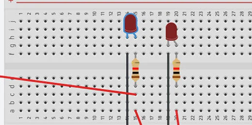
Let’s add another LED to help us with the comparison. Add another LED to the right of the current LED. Add a resistor and make all the same connections. There is one change we need to make. Don’t connect the resistor to the terminal rail.
Each LED needs to be controlled by a separate PIN. Connect the wire from the resistor directly to the GPIO pins on the Arduino. The original LED remains connected to PIN 6. Connect the other LED to PIN 3.
Open the code panel. Add another set pin code block. Place it after the existing code block. Set the pin to 3. Set the value to 255. Start the simulator.

That doesn’t help too much. There is a slight difference.

Stop the simulator. Change the variable for the first LED to 64. Start the simulator.

The difference is a little easier to see.

Pulse Width Modulation
What is pulse width modulation? It turns out that pulse width modulation is a sneaky way to simulate a lower voltage. This is easier to understand by using an oscilloscope. Oscilloscopes display the change in electronic signals over time. The oscilloscope will show us the voltage going through the circuit.
Click the Code button to close the code panel.

Click in the components search box. Type oscilloscope. Select the oscilloscope.

Place the oscilloscope on the left side of the breadboard. Adjust the size of the components so the oscilloscope is visible.

The oscilloscope has connectors. Click the connector on the right to create a wire.

Connect the wire to the resistor before it connects to the LED.
Move the LED up to make room for the next wire.
Connect the wire from the negative terminal of the oscilloscope to the cathode of the LED.

Click on the oscilloscope to select it.

Go to the oscilloscope configuration box. Change the measurement from ms(milliseconds) to (us)microseconds.

Change the time per division to 500. These parameters will display the frequencies from the voltage in 500-microsecond increments.

What is a microsecond? Think of a second. That is fast. A second is divisible into smaller time units. The next level of time is in milliseconds. There are one thousand milliseconds in one second. A microsecond is a millionth of a second. One million microseconds make one second. That is very fast.
Electricity travels very fast. Choosing microseconds slows things down so we can see the patterns on the oscilloscope.
Open the code editor. Change the variable to 255.

Start the simulator and look at the oscilloscope. A blue line appears on the oscilloscope. This line represents 4.85 volts.
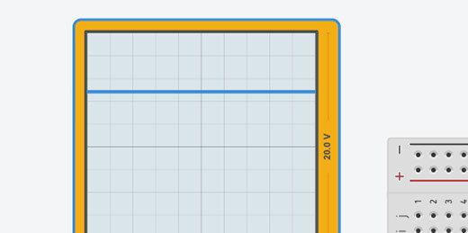
Stop the simulator. Change the variable to 0. Start the simulator. The blue line is in the middle. This represents no voltage going to the LED.

Stop the simulation. Change the parameter to 128. Start the simulator again. The simulator shows lines going up and down.

Let’s take a closer look. When a line appears at the top we know it represents 5-volts. A line at the center represents 0-volts.
This line isn’t flat. The line is at 4.85-volts for a time and then at 0-volts for another time.

The screen has a grid. The vertical lines represent 5ms. The gap between each line is 5ms long.

The oscilloscope shows that the voltage is zero for 5ms and then it is 4.85-volts for another 5ms. This pattern repeats.

Let’s think about what is going on. The voltage changes from 0 to 4.85 very quickly. This is like flipping a light switch on and off very fast. The LED is fully light for 5ms then off for 5ms. It is on half the time. The value we placed in the parameter is 128. This represents half the available voltage going to the LED.
Arduino is flipping the voltage on and off to simulate half the voltage going to the LED.
Stop the simulation. Change the parameter to 64. Start the simulation again. The bars in the simulation at the top are shorter than those at the bottom.

A short bar at the top represents a short time where the voltage is 4.85-volts. A longer bar at the bottom represents the voltage at 0-volts.
How long do you think the voltage is set to zero? The space between the vertical lines is 5ms. The line extends about halfway into the next space. This is roughly 7.5ms. The LED is off for 7.5ms and on for 2.5ms.
The parameter of 64 represents one-quarter of the total voltage. Think of it this way. A value of 128 is half of 256. A value of 64 is half of 128 and a quarter of 256. The LED is on for one-quarter of the time and off for the remainder, three-quarters.
The LED is on for less time and this causes the LED to look dim.
Our human eyes don’t see this pulsing. The pulses are so fast that our eyes take an average of what is going on. We don’t see a blinking LED but a dim LED. This is why we need an oscilloscope. To slow things down.
The voltage is pulsing through the LED. Probably where the name Pulse Width Modulation came from.