Electric circuits and Arduino with TinkerCAD

Coding Circuits With Arduino in Tinkercad
An Arduino is a microcontroller. A microcontroller is a very simple computer that accepts basic code. It translates that code into instructions that interact with the physical world. In this lesson, we will use a microcontroller to act as a switch.
Click the link below to see the completed project.
https://www.tinkercad.com/things/3sufhjgf15T
Create a new circuit in TinkerCAD. Add a Breadboard to the work area. Place one LED on the Breadboard and place two jump wires. Connect one jumper wire to the positive rail. Connect the other to the negative rail. Make sure to connect the anode to the positive lead and the cathode to the negative lead. The Anode on the LED is the the one with the bent wire.
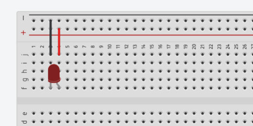
LED on breadboard
Click on the Components button and find the Arduino Uno R3 microcontroller.

Arduino Uno R3 component
Place the microcontroller to the left of the Breadboard. Several components are part of the Arduino board. Let’s look at a couple of these components.
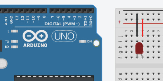
Arduino alongside the breadboard and led circuit.
The holes along both sides of the board are GPIO pins. This stands for General Purpose Input/Output pins. Each is a connector that links to our Breadboard with a jumper wire. Most of these are with a number. These numbers identify the pins in our code. The code we develop on the board can reference these pins as either input or output. There is one connector labeled GND. This is the ground connector or the negative terminal in our circuit. The Arduino provides coded instructions to the components on the board. It also provides the necessary current to make the components work. The GND is the same as the negative terminal on a battery. The other connectors marked with a number are the same as the positive terminal on a battery.
A physical Arduino board connects to a five-volt power supply from a computer USB port. The Arduino itself supplies the same 5 volts to components. For some components, this is too many volts. In our example, the 5 volts will destroy the LED on the Breadboard. We will be adding a resistor to limit the amount of current going to the LED.

GPIO PINs on Arduino
Connect a jumper wire from the GND connector on the Arduino to the negative rail on the breadboard. Take another jumper wire and connect it from the number 3 GPIO to the positive column. I moved the board so you could see the connections. I also color-coded the wires.

Jumper wires from breadboard to Arduino.
This isn’t enough to turn on the LED. We need to do a few more things. Click on the Code Editor button.

Code editor button
A coding panel will open at the bottom of the page. We use blocks to develop code. Like the blocks used in Code.org or Scratch. There is already a program in the editor. This is the standard code included each time we place an Arduino board onto the workspace. This code instructs the LED on the Arduino board to blink. This is not the LED on our Breadboard. The Arduino has a small LED on the board. Click the Start Simulation button to see the LED on the board blink.

LED code block for Arduino.
The blinking LED is on the left side of the Arduino logo. Stop the simulation.
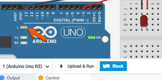
Blinking LED on Arduino board.
We don’t need this code. We want to control the LED on the Breadboard. Click on the first code block and drag it to the trash can icon. This takes everything that is connected to it.

Removing the standard LED code.
We need a little more room to code. Move your mouse pointer to the top edge of the coding panel until you see the arrow change. Click and drag up to expand the coding panel.

Widen the code area.
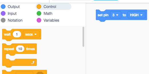
The coding panel has different sections of code. We will be using code blocks in the Output section. Drag the set pin code onto the coding canvas.
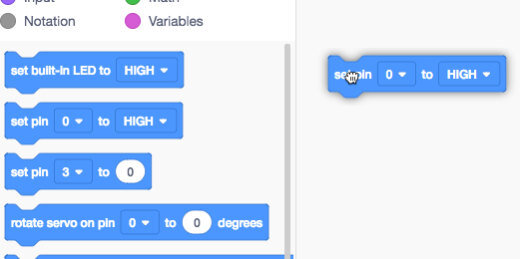
Set pin code block onto canvas.
Most code blocks have options. This code block includes a PIN and a state. The PIN references the connector we used to send current to on the Breadboard. This is the positive jumper wire we connected earlier. We connected the wire to pin 3. The options in the code block are arguments.
The term argument comes from mathematics. The argument of a function is a specific input to the function. It is an independent variable like the pin in our code block. This code block has two arguments.
Set pin code and parameters.
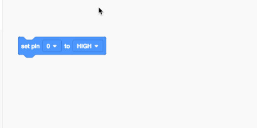
Change the pin to 3. The second argument has two states. A state has one of two options. A state can be on or off. The state is set to high. A high state is the same as ON. The other option is a LOW state. This is the same as OFF. Computers read everything as either ON or OFF.
That’s all we need to get started. Click the Start Simulation button. Resize the code block panel to see the LED.

Parameter set to pin 3.
The LED will change color to show that it is on. There is an exclamation mark next to the LED. This exclamation mark is a warning. The current going through the LED is too high. In the simulation, we get a warning. In a physical board with a real LED the LED would burn out and won’t work again. This is why testing or prototyping is useful. LEDs aren’t expensive but expensive enough that you don’t want to be burning them out all the time.
To avoid burning out LEDs we need to use resistors. Resistors restrict the flow of current to components. Every circuit includes voltage, resistance, and current. Current is the part of the equation that does all the work. Think of electric Current like water flowing through a river or stream. Resistance is the width of the river or stream. Narrow streams have more resistance than wide streams.

LED light with warning.
Stop the simulation and close the code editor. We need to make room for the resistor. Move the LED to the other side of the board. Place it in column A.

Changed position of LED on breadboard.
Open the components panel and find the resistor.

Resistor in component panel.
Place the resistor so it bridges the gap between the two halves of the board. Make sure the resistor is in the same row as the anode and the positive jumper wire.

Resistor on breadboard.
The row connections do not span across the board between E and F. Add a jumper wire to complete the circuit.

Jumper wire to complete circuit.
Run the simulation and the LED should light.
Blinking LED
The code we used in the previous example turned the Arduino into a glorified switch. We can do so much more with Arduino.
Click the code editor button to open the coding panel. Click the Control code block category and look for the wait code block.
Wait code block.
Place the wait code block below the set pin code block. The wait argument is set to one second. Leave the argument at this value. Go back to the Output code block category. Place another set pin code block onto the canvas below the wait code block.

Second set pin code below wait block.
Set the pin value to 3 and the state to low. Run the simulation. The LED will turn ON and OFF. The OFF state is too short. Arduino is a very simple computer but it is still very fast. It processes our instructions in fractions of a second. We need to instruct the code to slow things down so we have time to see the changes.

Set pin block with updated parameters
Go to the scripts panel and find a wait code block. Add a wait code block after the last pin code blocks. Leave the wait value at one. Run the simulation again. The LED will turn on and off over and over again. The code we write does not include a loop function but the Arduino repeats the code anyway.

Second wait code block
The code blocks we use are representations of written code. The written code is on the right side. The code has two main sections or functions. The void setup function sets pin 3 as the output pin for the instructions.
The void loop function is where we write the main part of our code. The void loop repeats the code until the simulation stops. On a physical Arduino, we need to turn the power OFF.

The script represented from the code blocks
The void loop instructs the board to set the power to pin 3 to high or On then wait one second. After one second the power to pin 3 is set to low or turned off and then wait one second. The instructions repeat all over again until we stop it by removing power from the Arduino board.