
Technology lessons for educational technology integration in the classroom. Content for teachers and students.
Elapsed time, velocity and the Micro:bit
In this lesson, we are going to use the magnetic sensor to calculate the velocity of a car moving across a track.
This is the setup. I have a toy car, Hot Wheels, with a magnet attached to the roof. The car is on a Hot Wheels track. Next to the car and track is a sensor gate. The sensor gate has a Micro:bit. The micro:bit will use the magnetic sensor to detect the passage of the car and magnet through the gate. A small distance away is another sensor gate. This gate is also set to detect the passage of the car and magnet.
The micro:bit will start a clock when the car passes through the first gate. The clock will stop when the car passes through the next gate.
Knowing the distance and time between the gates will help us calculate the velocity of the car. The micro:bit will provide the time it took the car to travel a specific distance. It will be up to us to calculate the velocity.
Disclaimer
I am not affiliated with Hot Wheels or the company that represents Hot Wheels. You don’t have to use Hot Wheels. I like to use them because they are small, inexpensive, and include tracks.
The gates
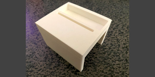
I designed the start and end gates with Tinkercad. The design is free to download and print. The links to the models and preview of each model are available in the resources section.
The first gate is designed to have enough clearance for a regular Hot Wheels car and a small magnet. The gate has a bed to hold the battery pack. The gate prints upside down so you don’t have to worry about removing supports.

The second gate is not designed to be a gate specifically. I use this to hold the micro:bit for a variety of activities. The holder is available in two formats. One format holds the regular AAA battery holder. The other format holds the lithium rechargeable battery.


The cars and tracks are available online. I found the best prices on Amazon.

The magnets are also available on Amazon. You can get the cars, track, and magnets for less than fifty dollars. You don’t have to use the 3D printed gates. Use small cardboard boxes or structures build with popsicle sticks.
I’m not providing links to the resources on Amazon because links tend to change and suppliers tend to disappear.
Code Resources
Transmit Gate code (Make Code):
https://makecode.microbit.org/_DDhaW6diba5i
Transmit Gate code (Github):
https://github.com/digitalmaestro/startgate
Receive Gate code (Make Code):
https://makecode.microbit.org/_42eAezdFw0K0
Receive Gate code (Github):
https://github.com/digitalmaestro/finishgate
3D print resources
enclosed gate
Enclosed Gate preview
Enclosed Gate download (Thingverse)
https://www.thingiverse.com/thing:4837474
Enclosed Gate download donate at Cult 3D
micro:bit holder
Micro:bit holder with lithium battery support preview:
Micro:bit holder with lithium battery support (Thingverse)
https://www.thingiverse.com/thing:4837487
Micro:bit holder with lithium battery support donate at Cults 3D
Micro:bit holder with AAA battery support preview:
Micro:bit holder with AAA battery support download at Thingverse
https://www.thingiverse.com/thing:4837494
Micro:bit holder with AAA battery support donate at Cult 3D
Magnetic direction and strength
The sensor on the micro:bit is located behind the buttons. The sensor is part of the chip dedicated to the compass. Version 1.3B has the chip near the extreme left edge.

Version 1.5 has the chip on the left edge too. It is integrated into one chip that contains both the accelerometer and compass.

Version 2.0 has the chip in the same general location. It is a little larger than the others.

The sensor readings will be stronger when the magnet is closest to the sensor. In my lesson, the car will travel from right to left. The sensor is on the right side when the micro:bit is facing this direction. The sensor will detect the magnetic field almost as soon as the car is next to the micro:bit.

The strength of the magnetic field depends on the size and type of magnet.
This part of the lesson will gather information on magnetic field strength. We will use that information to set up the conditions for starting and stopping the timer.
We need to know the approximate strength of the magnetic field when the car is closest to the starting position. We want the starting position to be close to the right edge of the Micro:bit. This will start the timer as soon as the car enters the gate.
Use the link below to access the Make Code development page.
Click the New Project tile.

Use ‘magneticStrength’ for the project name; click the Create button.

The start gate will send a signal to the finish gate when the car enters the magnetic field. We need to know what that information looks like before creating the code.
The micro:bit measures the strength of the magnetic force from three directions. The measurements are along the x, y, and z-axis.
The x-axis runs left to right along the long edge of the Micro:bit.

The y-axis runs up and down along the short edge.

The z-axis runs through the Micro:bit.

We are going to collect information from one of these directions. This information will be stored in a variable.
Go to the Variables code category; click the ‘Make a Variable’ button.

Use ‘x-axis’ for the variable name; click the OK button.

Three blocks are created for each variable. The first block is the variable itself. The Set block is used to assign values to the variable. The values can be numbers, letters, or operations. The Change code block is used to change variables with numbers with some regular amount.

Get the [set x-axis] code; place it in the [forever] loop.
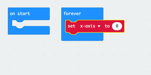
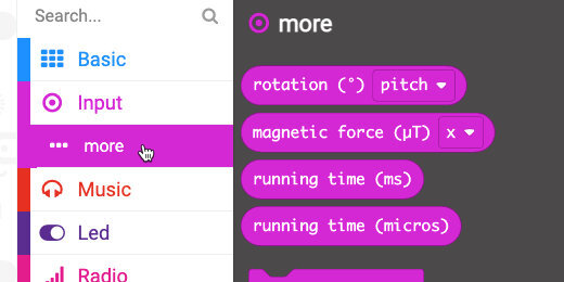
Select the Input category and then the more option. Look for the [magnetic force] code block.
Place the code block into the set variable parameter. The block is already set to get values from the x-axis.

The value in the variable will continuously update. We won’t display the information on the micro:bit display. This would take too long to get the information we need.
We are going to send the information directly to the computer, which can display information faster. The information is sent along the cable. The cable is a Universal Serial Bus, USB. There is a code block that sends information along the Serial cable.
Click the Advanced code category button.

Select the Serial code category.
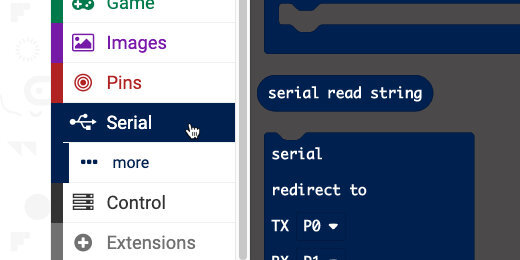
Find the [Serial write value] code block.

Place the code block in the [forever] loop; after the set variable code.

Type x-axis into the value label field.

Go to the Variables category. Get the [x-axis] variable; place it into the value field.

This is all the code we need to collect the magnetic field strength along the x-axis.
Connect your micro:bit to the computer. Click the Action menu and select ‘Download to micro:bit’.

Leave the micro:bit connected to the computer.
A ‘Show console Device’ button appears in the simulator area. Click the button to open the console.

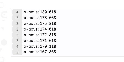
The bottom of the console displays the stream of magnetic field values detected by the sensor.

A scrolling chart plots the values as they increase or decrease.

Get a small magnet and move it along the bottom of the Micro:bit. The numbers will go up and down.
Sometimes the values will change from positive to negative.

Magnetic field strength
We are not interested in the value from one axis. We want to get the overall magnetic field strength from the magnet. This will assure that we won’t miss the start and finish as the car passes through the magnetic field.
Click the ‘Go back’ button.

Click the force axis selector; choose strength.
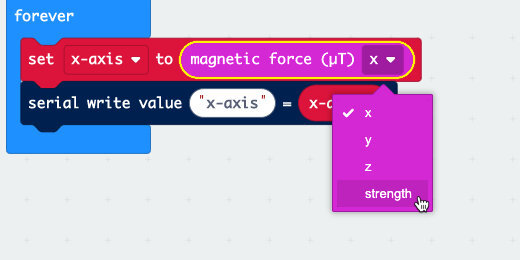
Change the value label to ‘strength’.

Click the variable selector; select ‘Rename variable’.

Use ‘strength’ for the variable name.

Download the updated code to the Micro:bit; click the ‘Show console Device’ button.
Move the magnet around the micro:bit to find the point where the magnetic force is strongest. It should be strongest along the right bottom edge.

The strength is over 1,000 when the magnet is near.

Move the magnet about an inch away.

The strength value drops by over a thousand with my magnet.

We only need to look for a moderate increase in the magnetic strength.
There are times when the measurements appear as negative values. We will fix this in our code later.
Click the ‘Go back’ button. Click the Home button to return to the Make Code main page.

Start gate
The start gate has the simplest task. It will sense the magnetic field strength from the magnet. When the detected magnetic field is at a specific strength it will trigger a message. The message is sent to the second gate. The second gate micro:bit takes care of starting and stopping the timer. It will also display the elapsed time.
Click the ‘New project’ tile.

Use ‘startGate’ for the project name.

This micro:bit will send a signal to the finish gate. We need to activate the Radio function. The Radio function is used by one micro:bit to send information to another.
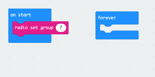
Select the Radio code category; find the [radio set group] code.

Place the code into the [on start] section.

The radio group is a number. This number is like a channel. There are 256 possible channels, 0-255. We can use any channel. All the Micro:bits that need to communicate with one another must be using the same channel. Set the radio group to channel 7, just for practice.
The micro:bit needs to decide when to send the message. Decisions are made using deductive logic. This logic is in the form of, ‘If something is True Then perform some action’.
There is more information on if-then statements on the CK-12 website. https://bit.ly/3nzyGJy
Go to the Logic category; look for the [If True Then] code block.

Place the code into the [forever] loop.

The True parameter in the logic condition is another logic operation. This is where we look for a value or a comparison.
Go back to the Logic category; find the Equal comparison code.

Place the comparison code into the True parameter.

Go to the Input codes and get the [magnetic force] code.

Place the code on the left side of the comparison code.

Change the force input from the x-axis to strength.

Use the comparison selector to select ‘greater than or equal to’.

We know that the magnetic strength can reach a strength of over 1,000. We also know that the strength can go down to less than 100. A value in the middle of this range would be a good way to determine the presence of the car and magnet. Enter 500 into the right side of the comparison.

If the magnetic strength is equal to or greater than 500, we want to send a signal to the other Micro:bit.
Go to the Radio codes; find the [radio send string] code.

Place the code inside the condition.

Type ‘team1’ into the string assignment.

I am using a keyword for the string. This keyword serves an important purpose. It provides a codeword that verifies the authentication of one micro:bit to the other.
This verification is important in the classroom. Students often forget to set the radio channel to anything other than channel 1. It is also possible that students or groups might select the same group number. Even if multiple Micro:bits are using the same radio channel, the keyword provides a verification before a message is accepted.
Go to the Basic code category. Find the [show icon] code block.

Place the icon code after the radio send code.

Click the icon selector and choose the Happy icon. This provides feedback so we know the magnetic strength was detected and exceeded the 500 microteslas we selected.

Return to the Basic codes and find the [pause] code block.
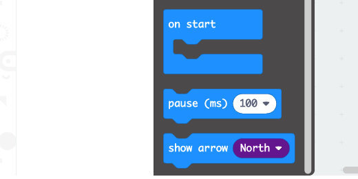
Place the code block after the icon code.

Click the time selector; choose 500 milliseconds.

Get the [clear screen] code block from the basic section; place it after the pause code.

We need the pause and clear code to erase the icon after displaying the confirmation. It clears the display for future trials.
We should identify this micro:bit as the start gate. Get the [show string] code from the Basic code category. Place the code into the [on start] section.

Replace the hello string with the letter ’S’.

Connect the micro:bit to the computer. Click the action menu and select Download to micro:bit.

Eject the micro:bit and set it to one side. Let’s get to work on the code for the other Micro:bit.
Finish Gate
Click the Home button to return to the Make Code micro:bit home page.

Click the New Project tile. Use ‘finishGate’ for the project name.

Get the [radio set group] code from the Radio category. Place the code into the [on start] section. Change the radio channel from 1 to 7.

This micro:bit listens for a message sent from the start gate micro:bit. Go to the Radio codes; look for the [on radio received ‘receivedString’] code block.

Place the code block on the canvas.

When the micro:bit receives a string, we need to verify the string. This is another example where we need a condition to check for something to be True.
Get the [if True then] code block; place it into the [on radio received] code.

Go back to the Logic codes; find the string comparison code. This code has quotes inside each side of the comparison parameters.

Place the code into the condition parameter.

Type ‘team1’ into the right side of the comparison.
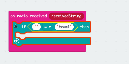
The ‘receivedString’ block on the [on radio received] code is a code block variable. It holds received signals from micro:bit devices.
Drag the code block from the [on radio received] parameter; place it into the left side of the comparison code.

The code verifies that the string received matches the string we need to start the timer.

When the string is received, we need to capture the current elapsed time on the micro:bit. The elapsed time is measured in milliseconds. There are one-thousand milliseconds in one second. The time will be saved to a variable.
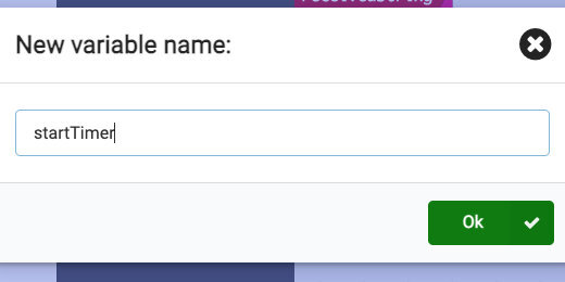
Go to the Variables category; click the ‘Make a Variable’ button.

Use ‘startTimer’ for the variable name.
Get the [set ‘startTimer’ to] code; place it into the condition statement.

Go to the more code section of the Input codes; find the [running time (ms)] code block.

Place the code into the value assignment parameter of the [set ‘startTimer’ to] code.
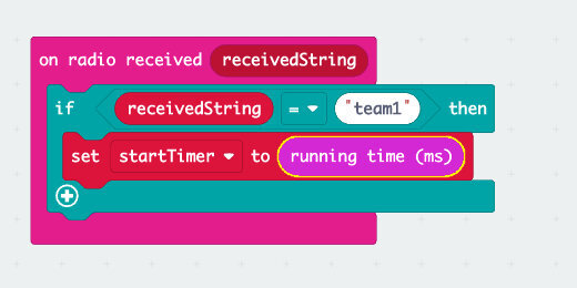
The current running time is stored in the [startTimer] variable. We need feedback to know this has been done. Go to the Basic codes; get the icon code block. Place the code after the set variable code. Leave the icon set to the heart.

This code gets the running time value from the micro:bit the moment it receives the message.
Review of what is happening
This is how it works. Let’s assume the start micro:bit sends the signal and it is received by the finish gate micro:bit. Let’s assume that the finish gate micro:bit has been running for 8000 milliseconds, 8-seconds. This value is stored in the variable ‘startTimer’. The car activates the sensor on the finish gate after 11000 milliseconds, 11-seconds.
We subtract the second reading, 11 seconds, from the first, 8 seconds. This gives the total elapsed time since the timer was triggered by the start gate.
Finish time
To get the finish time, we will create some code that is similar to the one from the first gate. The code will be in the [forever] loop so it is always looking for a change in the magnetic field strength.
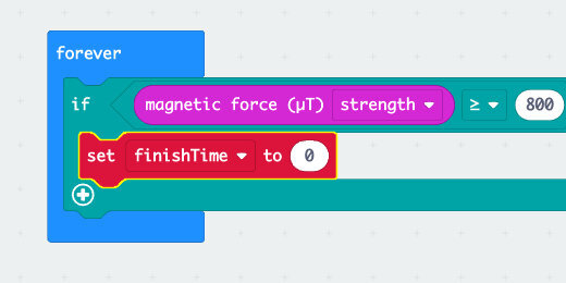
Go to the Logic codes and get the [if True then] code block. Place the code into the [forever] loop.

Get the comparison code; place it into the True condition parameter.

Change the comparator to greater than or equal to.

Get the [magnetic force] code from the Input codes; place the code into the left side of the comparator.

Change the force vector to measure the strength of the magnetic field.

Enter the magnetic field strength you want to sense into the comparator. This can be the same value we used for the start gate.

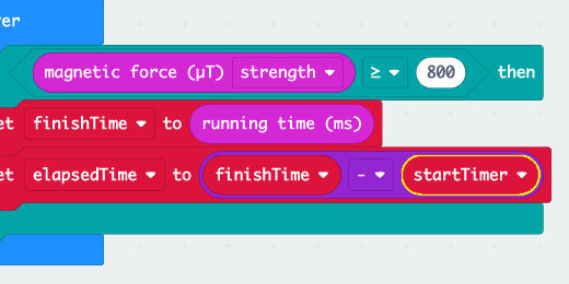
We want to record the current running time when the car is close to the gate. This information will be stored in another variable.
Go to the Variables category; click the ‘Make a Variable’ button. Set the name of the variable to ‘finishTime’. Place the [set ‘finishTime’ to] code into the condition statement.
Get the [running time (ms)] code from the Input category. The code is under the More codes option. Place the code into the value assignment for the ‘finishTime’ variable.

We have the first running time saved in one variable and the second time saved in another. We can now subtract these values to get the time it took to travel from the first gate to the second.
We need another variable to store the results. Go to the Variables category. Create a new variable; use ‘elapsedTime’ for the variable name. Place the [set ‘elapsedTime’ to] code after the other set variable code.

Go to the Math code category; find the subtraction operation.

Place the operation into the assignment parameter for the [set ‘elapsedTime’ to] code.

Get the ‘finishTime’ variable; place it into the left side of the subtraction operation. Get the ‘startTime’ variable; place it on the right side of the operation.
convert seconds
The difference is calculated and represented in milliseconds. We can keep the answer in milliseconds, but I think it is much better to get the result in seconds. To convert milliseconds to seconds we need to divide by 1000.
We need another variable to store the answer. Go to the Variables category. Create a new variable; use ‘seconds’ for the variable name. Place the [set ‘seconds’ to] code after the [set ‘elapsedTime’ to] code.

Go to the Math codes; get the division operation. Place the operation into the assignment parameter for [set ‘seconds’ to].
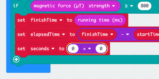
Get the [elapsedTime] variable; place it into the left side of the division operation. Enter 1000 into the right side of the operation.

A confirmation
We need a way of knowing that the magnet’s passage recorded and the micro:bit calculated the elapsed time. Get the [show icon] code; place the code after the last code in the condition statement. Change the icon to a checkmark.

The elapsed time
Go to the Input category; find the [on button A pressed] code.

Place the code on the workspace.

Get the [show number] code from the Basic code category; place it into the [on button A pressed] function. Get the [seconds] variable; place it into the show number parameter.

Identify the micro:bit
We need to identify this micro:bit as the finish gate. Place the [show string] code, from the Basic section, into the [on start] section. Use the letter ‘F’ for the string value.

Absolute field strength
We need to take care of one more item. During our magnetic field strength at the beginning of the lesson, we noted that the values sometimes flipped from positive to negative. We need to take care of that to avoid false readings.
This is what could and does happen, at least during my trials. A magnetic value of (-900), negative 900, will not trigger the code to start or stop the timer. This happens because negative 900 is not greater than or equal to positive 500.
Go to the Math code category; find the [absolute of] code.

Place the code above and to the right of the [forever] loop, not in the loop.

Get the [magnetic force] code and place it into the [absolute of] parameter.

Get the code blocks and place them back into the left side of the comparator.

Click the action button and download the code to the micro:bit. Eject the micro:bit. Click the Home button.

Open the ‘startGate’ project. Connect the start gate micro:bit.

Get the [absolute of] code block; place the [magnetic force] code into the parameter. Place both blocks back into the comparator. Download the code into the micro:bit.

Off to the races!
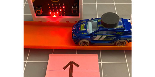
The image below shows the car on the track. The car and track are against the gate to get the best signal strength possible.

The happy icon appears when the magnetic force is greater than or equal to 500.

The finish gate shows it is waiting for the timer signal.

The heart icon shows the timer message was received.

Once the car enters the gate, a checkmark icon appears to indicate the magnet was sensed and the elapsed time was calculated.

Press button A to display the elapsed time.

Calculating velocity
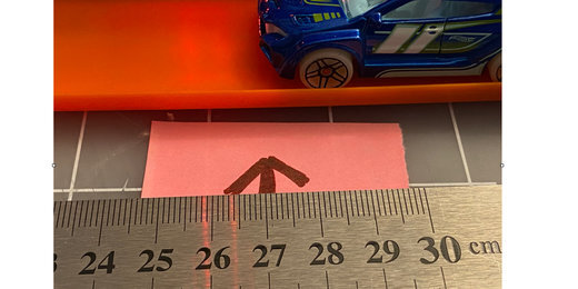
To calculate the velocity we need one more piece of information. We need to know the distance between the gates. It helps if we can get a good measure of the distance. We need to know the point where the start and finish gates record the running time.
Place the finish gate next to the track where it will record the finish. Move the car slowly up to the gate. Stop when the checkmark appears. Place a mark to show the point where the front of the car marks the finish line. Repeat the process with the start gate.
Get a ruler and measure the distance between the two marks.
Final notes
Be careful not to bring a magnet close to the finish gate after it has recorded the elapsed time. This will cause it to update the elapsed time with new values.
Enhanced Dice App Lesson 2
In this lesson, we continue from last week's lesson. Last week we organized our code in preparation for a larger project. We are moving over to the sprites and adding basic animation.

Enhanced Dice App Lesson 2 of 5
Dice animation
In this lesson, we continue from last week's lesson. Last week we organized our code in preparation for a larger project. We are moving over to our sprites and adding basic animation. The dice will spin and change face values as they spin. We will return to the button code and include a variable to set the rotation angle.
Click on the "Die1" sprite. Go to the Motion section. Attach the turn clockwise code block to our code. Repeat the process with the "Die2" sprite. Choose the counterclockwise code.
Click the Roll button to test the code. The dice images spin. This works fine but they land at awkward angles. The dice rotate fifteen degrees during each loop. They go through the loop ten times. The dice rotate a total of 150 degrees. For the dice to land flat they need to land at a 90-degree angle. We can choose multiples of 90-degree angles. The possible angles include 90, 180, 270, and 360. If we leave the number of loops set to ten, we can set the angle of each rotation to 9, 18, 27, or 36. We can try each of these to find one that we think works well.
The values in our turns are manually entered into each dice sprite. This isn't efficient or convenient. We need to create a variable that will pass a value to each turn without having to constantly go and change the value in each sprite. Go to the variables section. Create a new variable. Name the variable rotation.

Place the rotation variable into the "Die1" and "Die2" sprites code.

Go to the "rollButton" sprite. Place the set variable block in the loop below the last code. Change the variable to "rotation".

Set the rotation parameter to 18. This will rotate the dice and they should land flat after rotating 180 degrees. Click the Roll button.

The dice spin but they still land at the same awkward angle. The code is working fine. They are at this angle from the previous code we used. We need to make sure to reset the rotation of the blocks before running the program. This is part of what we do with all programs. We set the default values.
Properties for sprites need to be associated with each sprite. To reset each dice sprite we need to insert reset instructions into each. Click the "Die1" sprite. Place a "when I receive…" code on the stage. This code is in the Events section. The code is not attached to our existing code. It stands on its own.

Click the message selector and create a new message. Set the message name to "reset". Select this message in the message received event.

Attach a "point in direction…" code block to the reset message received. The "point in direction" code is in the Motion section. The direction is set to 90-degrees. Click on the "Die2" sprite and repeat the process. You don't have to create a separate variable for the message. Use the same variable.

Go to the "rollButton" sprite. Place a broadcast code block before the repeat code. Change the message to reset. Click the Roll button. The dice will spin and display a random face value. The dice will land at a 90-degree angle.

That’s it for lesson two. In the next lesson we will add sound to the dice app.
Sphero's volume and surface area
Sphero is a sphere with volume and surface area. To calculate this information we need one piece of information. We need to know the radius.

Basic math to understand Sphero’s geometry
Sphero is a sphere with volume and surface area. To calculate these values, we need one piece of information. We need to know the radius.
The radius is the distance from the center of the sphere to any point on the surface. We know that a line drawn from one point on the surface through the center and to another point is the diameter. The radius is half the length of a diameter. This information is similar to that of a circle.
There isn't a way for us to measure the radius of our sphere. We would need to disassemble the robot. We can, however, measure around the sphere. There are two values that we can measure. Both of these values will help determine the information we need.
Let’s begin with the easiest. For this exercise we will need a length of string. The string should be at least twelve inches long. The string shouldn't be too thick.
Find the seam along Sphero’s surface. Place one end of the string on a point on the seam. Wrap the string around the seam until it meats up with the string’s starting point. Use a marker or pen. Mark where the string meats the starting point. This measurement isn’t very accurate but we will round our measurement later.
Use a ruler. Place the starting end of our string at the beginning of the ruler’s measurement. Lay the string along the ruler. Find where the point we marked the string lays on the ruler. This is the circumference.The circumference from the measurements of my Sphero resulted in approximately nine and a quarter inches, 9.25in. The equivalent measurement in centimeters is 23 cm. Most rulers have both units of measure.
To determine the radius we need to use the formula for the circumference of a circle. The formula multiplies the diameter by Pi. To solve for radius we need to reformat our formula. This step takes us into the use of algebra.
We want the diameter to be on one side of our equation. Let’s begin by writing down our values into the equation. Take the value of the measurement and write it down. Place an equal sign to the right and then the value of pi, 3.14. Place the multiplication symbol to the right of pi and D for diameter.

We need to move the value of pi to the left side of the equal sign. To do this we need to divide by pi. Place a divisor and the value of pi under the circumference. Place a divisor and the value of pi under pi.
When we divide a number by the same number the answer is always one. Pi divided by Pi is one. One times the diameter is the diameter. We don’t need to write the number one.

Dividing the circumference by pi gives us the diameter. The diameter in inches is approximately 2.945 inches. The diameter in centimeters is approximately 7.324 cm. The value we get here is an approximation. The diameter is twice the radius. To get the radius we divide the diameter by two. The radius in inches is 1.473 in. The radius in centimeters is 3.662 cm.
Rounding the values for radius would seam to be reasonable but we will stay with this to review operations with decimal values. With the radius of our sphere we have the information needed to solve for surface area and volume.
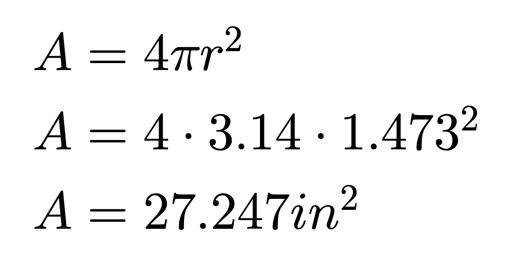
The surface area of a sphere is calculated by squaring the radius. The product is multiplied by pi. This product is then multiplied by four. We’ll use my measurement in inches first. The radius from my diameter of 2.945, is 1.473. This gives us an approximate surface area of 27.247. We must state the units of measure in the answer. The complete answer is 27.247 square inches.
The volume is calculated by cubing the radius. This value is multiplied by pi. That value is then multiplied by 4 and divided by 3. The volume is approximately 13.387 cubic inches.

Now we will calculate the surface area and volume using our measurement in centimeters. The radius from our diameter, 7.324 is approximately 3.662. The volume is approximately 205.704 cubic centimeters. The surface area is approximately 168.518 square centimeters.
Recalculate with rounding
The answers from our measurement of Sphero’s circumference are approximations. The string and ruler are not the most accurate tools. I used a Vernier caliper to measure Sphero’s diameter. A Vernier caliper is a ruler with a measurement scale. It is used to take precise measurements. With the caliper I measured Sphero’s diameter at 7 centimeters. Use this updated measurement to recalculate Sphero’s volume and surface area.

Here are my answers so you can compare. Sphero’s volume is 179.594 cubic centimeters. Round this to 180 cubic centimeters. The surface area is 153.938 square centimeters. Round the value to 154 square centimeters. I will use these values from this point forward.
The information we gathered in these math activities will be used in our science activities. Remember the values for volume because they will come up again later.
Blog banner image inspired by Freepik