Technology lessons for educational technology integration in the classroom. Content for teachers and students.
Tinkercad Transistor circuits
Transistors and LEDs have revolutionized our modern world. Transistors have made fast and small computers possible. In this lesson, we will learn to use the transistor as a switch.

Transistors
Transistors and LEDs have revolutionized our modern world. Transistors have made fast and small computers possible. In this lesson, we will learn to use the transistor as a switch.
Transistors have three leads. Each lead has a name and a purpose. The center lead is called the Base. The leads on either side are called the Collector and Emitter. You will see an image of this transistor later in the lesson. The location of the emitter and collector depend on the type of transistor being used. There are two types of transistors. Each transistor is referred to as either a PNP or NPN transistor.
The difference in the type of transistor depends on how it is manufactured. The NPN transistor is the most popular and common. Each end of the transistor is made of a semiconductor material that is saturated with electrons. The center material is depleted of electrons. This positively charged layer is sandwiched between two negatively charged layers. This is the transistor we will use in our lesson.
The PNP transistor is not as common. This transistor has a negatively charged layer sandwiched between two positively charged semiconductors.
For the transistor to work as a switch the base must receive electric current. The current stimulates the base to allow the flow of current across the collector and emitter. We typically have two power sources for a circuit with transistors. One power source activates the base and another source powers a component. Our first project will have one power source. The first project will help us compare how the second project with two power sources differs and the advantages of having two power sources.
Switches
For this project, we will need a breadboard, LED, resistors, button, and transistor. Create a new project. Place a small breadboard onto the work area. The first step is familiar. Attach a resistor to the board. One end connects to the positive rail. Add the LED so the Anode is on the same connection as the resistor. The current must flow into the LED through the Anode lead.
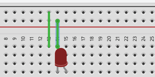
This circuit is going to have a few more components than our other circuits. I want to have plenty of room to keep things easy to see. Move the LED to the other half of the breadboard. Place it on the bottom of the board.

Use a jumper wire to connect the resistor to the Anode on the LED.

Get a 9-volt battery and attach jumper wires to the top half of the board.

We are using the lower half of the board too. Run jumper wires from each rail in the top half of the board to the lower half.
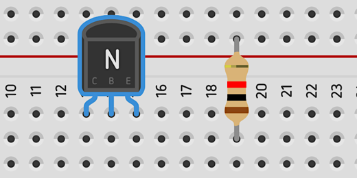
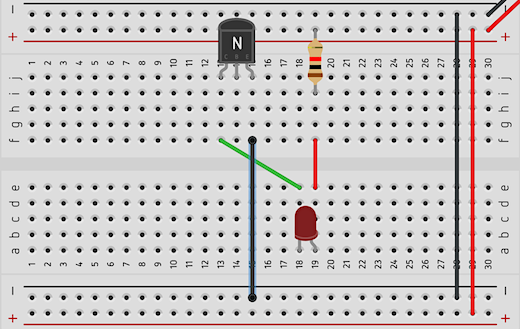
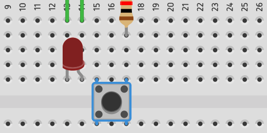
In the LED circuit, we placed a push-button between the Cathode and the negative rail. We are going to do the same thing here but we will use a transistor as our button to close the circuit. Find an NPN transistor in the components panel. It’s in the basic set of components.

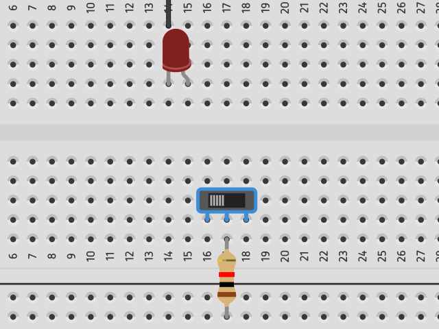
Place the transistor in the top half of the board next to the resistor. A transistor has three parts. It has a collector, base, and emitter. The transistor on our board has the letters C, B, and E to help identify the parts.
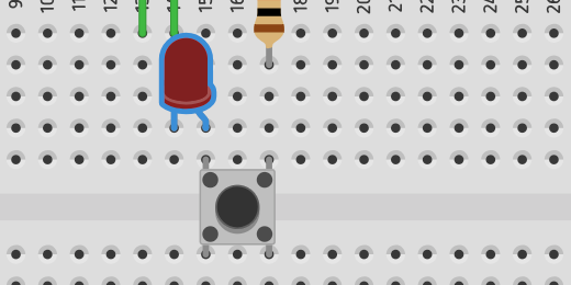
Connect a jumper wire from the Cathode on the LED to the Collector on the transistor. The Collector is labeled with the letter C.

Circuits run in loops. To complete the loop in this circuit we need to connect a jumper wire from the emitter to the negative rail. The transistor is large like the capacitor in our previous lesson. Instead of moving the transistor to attach a jumper wire we will attach it to the bottom of the board.
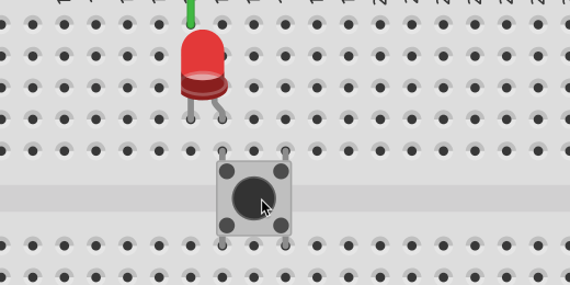
We don’t have a complete connection yet. Press the Start Simulation button. The LED doesn’t light because we don’t have a closed circuit. We need to pass current into the base of the LED to close the circuit.
Let’s take a moment to see how this circuit resembles a previous circuit. If we replace the transistor with a switch it looks like one in a previous lesson.
This is the part that makes it all work. Connect a resistor to the base of the transistor. The resistor will connect with the lower half of the board. Connect a jumper wire from the other end of the resistor to the positive rail. The current running from the positive rail through the resistor and base of the transistor is what activates the transistor.

Press the Play Simulator button. The LED will light.

The current flowing into the base of the transistor is what causes the transistor to close the circuit.
At this point we have a discussion noting the similarities and differences between a transistor, push-button, and switch. We discuss how the transistor is like a push-button and how it is like a switch.
Students have discussions in small groups. They discuss when a transistor as a switch would serve better over a regular switch. What are the advantages and disadvantages of using a transistor as a switch in a simple circuit?
Title the circuit Basic Transistor circuit and click the Tinkercad icon to return to the Tinkercad Circuits page.
This basic transistor circuit uses one power source to activate the transistor and light the LED. Let’s take a look at a circuit where we use a smaller current to pass a larger current to a circuit.
Amplification
The circuit for this lesson is similar to the one in the previous lesson. We don’t need to recreate the whole project. We will be using many of the same components.
We’ll make a copy of the previous circuit and use it for the next. Hover your mouse over the circuit preview of the previous project. Click the gear icon that appears in the upper right corner.

Select the Duplicate option.

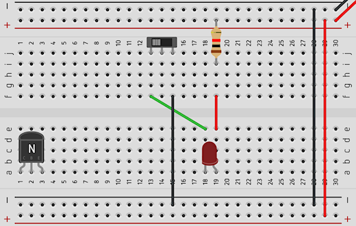
A copy of the circuit will be created and opened. The first thing we are going to do is replace the 9-volt battery with a AA battery. Click once on the 9-volt battery and press the delete key on your keyboard. Find a 1.5 volt AA battery and place it next to the board.
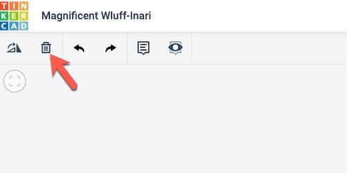
The terminals on the battery are at a right angle to those on the breadboard. I like to rotate the battery so the terminals are parallel.

There is a rotate button in the button bar next to the trashcan icon. Clicking the button will rotate a component clockwise. Make sure the AA battery is selected and click the rotate button once or twice. We need to do a lot of clicking to rotate the battery in this direction. Hold the Shifty key on your keyboard when clicking the rotate button to rotate counter-clockwise.
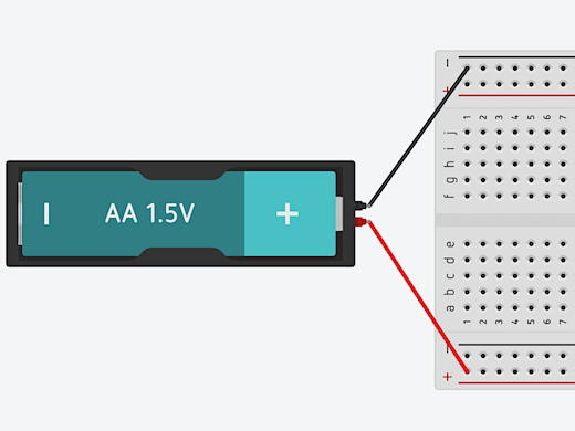
Connect the terminals to the board with jumper wires. The terminals don’t align so the wires will cross. This is where color-coding helps.

We reduced the voltage of the battery. In doing so we reduced the amount of current going to the circuit. Press the Start Simulation button to see the result on the LED. The light from the LED is fainter.

Stop the simulation and get another 1.5 volt AA battery. Place this battery on the opposite side of the board. Rotate the battery. Connect one jumper wire to the negative rail at the top of the board. Connect another jumper wire to the positive rail at the bottom of the board. This battery will serve as the source for the Base of the transistor. It will trigger the switch to allow current to flow through the transistor and circuit.
This battery provides the power source for the transistor base. We don’t need the power from the other battery yet. Remove the jumper wire connecting the battery on the right side of the board. Leave the wire for the negative connection. We still need a ground connection for the emitter.

We want the LED to shine brighter so we need more current. To get more current we need more potential energy in the form of volts. Click once on the 1.5 volt AA battery on the right side of the board. The configuration panel for the battery shows a count of one battery.
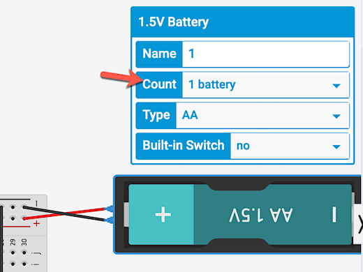
Click the battery count selector and choose 4 batteries.

Click the Start Simulation button. The LED is much brighter now.

Click once on the battery on the left side. Go to the configuration panel for the battery. Change the built-in switch option from No to Yes.

The battery will be enclosed in a case with an ON/OFF switch. Click once on the switch to turn the battery current OFF. This battery supplies current to the transistor. When current from this battery stops, the current to the transistor stops. This opens the circuit and prevents the current from batteries on the other side. No current means our LED won’t shine.

Circuits with Capacitors in Tinkercad
A capacitor is much like a battery. It stores current and releases that current when a circuit is closed. They don’t store as much current as a battery. Capacitors are reliable and don’t need to be replaced like batteries.

Capacitors
We will build on the skills we learned in the LED circuit. This circuit uses a capacitor. A capacitor stores current and releases it at a steady rate. The current in a circuit can change with power fluctuations, which can damage sensitive circuits. Capacitors are used to smooth out the current supplied to components and gradually reduce the current supplied to a component.
A capacitor is similar to a battery. It stores current and releases it when a circuit is closed. However, unlike batteries, capacitors don’t store as much current. Nevertheless, they are reliable and don’t need to be replaced like batteries.
This is an excellent time to discuss potential energy and kinetic energy. Batteries and capacitors store electricity, which is potential energy. The stored energy is released into circuits and provides kinetic energy. The amount of kinetic energy released is measured as current. The potential energy in batteries is measured in volts.
The potential energy in capacitors is measured in Farads. Capacitors store electrostatic charge. They don’t produce the current released. They store it and release it at a steady rate.
This resource has been relocated; use the link below.
Buttons and switches in Tinkercad circuit projects
Buttons and switches are used to complete circuits in electronic components. Tindercad has buttons and switches to close circuits in our simulated electronic projects.

Buttons in an LED circuit
A switch or button is used to close a circuit. Current in a circuit flows from the positive side of a power source to the negative side. A closed-circuit is required to enable the flow of electrons from the positive side of the battery terminal to the negative side.
We’re going to build on the same circuit from the previous article, A Basic LED Circuit with Tinkercad.
Go to the Components panel and look for the push button. It has a circle in the center of a square. Place the push button on the right of the LED. We will use the button to bridge the center division of the breadboard. Half of the button should be on one side and the other half on the other.
We need to move our components around the board to complete the circuit. Move the LED so the Anode lead is on the same row as the lead for the left side of the switch.
Move the resistor to the other side of the board. Align the resistor to the right lead of the push button. One end of the resistor needs to connect to the positive rail on the board.

We need to reposition the two jumper wires. The jumper wire that connects to the LED Cathode lead needs to connect to the negative rail.

Click once on the jumper wire. Circle handles appear at each end of the wire. Use the handle on the positive rail to move the end of the wire to the negative rail.
Click once on the jumper wire to the left of the one we positioned. Click and drag the top of the wire to the right.

Place the wire near the jumper wires for the battery. Connect it to the positive side of the rail.

Move the other end of the wire to the other side of the board and connect it to the positive rail too. This is how we distribute current to both sides of the board when using one battery.

jumper wire across breadboard
Let’s take a closer look at the push-button connection. Think of the button like a road with two lanes. Current flowing in each lane will flow uninterrupted. The current flowing through the right lead is not prevented from flowing through the button. The current cannot go to the other lead, the one on the left, unless the button is pressed. Pushing the button closes the circuit and current flows from the right lead to the left lead. Like a car changing lanes.

Press the Start Simulation button. Press the push button with your mouse to light the LED. Keep the button pressed on your mouse to keep the LED light. Release the button to turn OFF the LED. The LED remains light as long as we keep pressing the button.
Using A Switch
A switch is an option to light the LED without keeping our finger or the arrow on the push button. We’ll replace the push button with a switch. Click once on the push button and press the delete key on your keyboard. If the button isn’t removed, make sure the simulator is stopped. Go to the Components panel and find the switch.
Place the switch on the board. Place the center lead of the switch in the same row as the resistor. Place it in the column above the resistor.
The center lead on the switch is called the Common. This is where the current flows into the switch.

The leads on either side of the switch are called terminals. The lead on the left is called Terminal 1. The one on the right is called Terminal 2.

Connect a jumper cable from Terminal 1 to the Anode on the LED.

There is a slider on the switch. The slider is currently connecting the Main to Terminal 1. This is creating a closed circuit. Click the Start Simulation button. The circuit is closed and the LED will light.

Slide the switch to the right to turn the LED OFF.
Basic LED Circuit with TinkerCAD
TinkerCAD has a circuit development environment along with a simulator. The components are similar to actual components. This allows us to teach basic electricity and electronics concepts.

Introducing Tinkercad
Tinkercad is an online development tool for 3D models. It is also a development tool for electronic circuits. The development environment is easier to use than similar tools used by professionals. It’s intuitive for students. The lessons in this article will focus on the electronic circuit development environment. This environment has components to construct a variety of electronic circuits. We assemble and test these circuits inside the development environment.
There are many benefits to using an online development and simulation environment. The service is online so there is nothing to install. There is no specific browser requirement. The service is free. The components don’t break. We are free to make mistakes. The environment is safe. We don’t have to worry about students sticking themselves with the points of LEDs or transistors. No electronic shock from battery current.
A drawback is that the development and testing environment is digital. Studies have shown time and again the importance of kinesthetics. Kinesthetic learning is where students interact with their learning by touching and interacting with objects. Students are engaged in active learning.
In my experience, students learn better when they interact with the content. Using an online simulation is not enough. The online skills don’t always transfer from the simulated world to the real world. There are lots of reasons for this and one reason is the lack of context. Learned skills must be applied to real-world situations.
I recommend combining the online development of circuits with hands-on activities using real components and circuits. Electronic circuits are relatively inexpensive. A box of 300 LEDs on Amazon costs as little as $9 US dollars. A box of over 500 resistors costs about the same. An assortment of capacitors costs about 13 dollars. A pack of six mini breadboards runs about $5. Keep in mind that these are all reusable and can last years.
Find an old radio in a second-hand store and open the back. Expose the electric components. Don’t plug the radio to a power source when doing this. Remove any batteries too. Identify the components and discuss their purpose.
Studying the components in a circuit ties in very nicely when discussing systems. How do the components contribute to the functioning of the radio? How would the removal of one component affection the functions of the radio? How is this similar to other systems?
Login to the Tinkercad Circuit Environment

Tinkercad is free. Creating an account requires an email address. Students in districts with account integration through Google or Microsoft can log in with one of these accounts. The login option for Google or Microsoft is not immediately apparent. Let’s take a look at the process. Click the Sign In button.

Select the option to sign in with a social media provider account.

Select the Google or Microsoft login option.

Sign in with your email account credentials. If you are using a Google account and the Chrome browser then you will be presented with your account information. Click the account you want to use. Most people have one account. You might have multiple Google accounts. Just select your favorite.

The Tinkercad home page appears as soon as you log in. The home page begins with the 3D development environment. There is a menu on the left side of the page. Use this menu to navigate to the Circuits development environment.

The Circuits portal has a nice big green button. Click this button to create a new circuit.

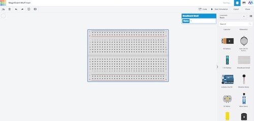
The Circuit Simulator

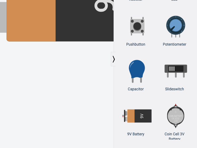
The circuit simulator is simple. The main area has a development canvas. All the available components are found in a panel on the right side. There is an extensive list of components. The basic components are displayed for us to create basic projects. Some of these components include LEDs, switches, resistors, and batteries. There is a search box above the component list. The search box is useful when we need to find a specific component in the much larger list of components.
There are four buttons above the list of components. One of the buttons is used to start the simulation after we construct a circuit. When everything is ready we press the Start Simulator button. This activates the simulated battery current. We need to press this button to begin the simulation every time. We need to stop the simulation when we want to make any changes to the circuit. Like in real life, we should not work on a circuit when current is flowing through it.
The Breadboard
A breadboard is used to develop circuit prototypes. It provides a place for us to connect components and hold them in place. Without a breadboard, we would have to connect components with clips or bare wire. These are not ideal ways to connect components. The breadboard makes the job of creating circuits much easier.
The term breadboard comes from the early days of electronics and prototype development. Hobbyists would use screws and nails on old breadboards to hold components and wires in place. Breadboards were made of wood. The breadboards used for electronic prototyping today are made from a plastic case. Inside the case, we have metal clips that hold components and wires.
For those of you that don’t know. A breadboard was at one time used to slice bread. This is when you made your bread or purchased bread at a bakery.
Before building projects on a breadboard we should find it in the components panel and place it on the work area. Scroll down the list of components and find the small breadboard. Click and drag the board onto the work area. We can also click the board once and it will attach itself to our mouse pointer. Place the board near the center of the work area.

Let’s take a closer look at the board. We must understand how the board works. The board is a plastic rectangular box. The box has holes placed in patterns.

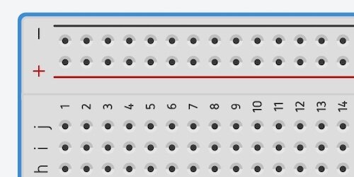
There is a series of holes between red and black lines. These holes are on opposite ends of the breadboard. The end of each line has a Plus or Minus symbol. The plus is red and the minus is black. These colors are important. They are a standard used by most circuit designs. The holes along the red line carry current from the positive side of a battery terminal. The holes along the black line carry current from the negative side of the battery terminal.
Let’s take a look at what is going on inside a breadboard. Under each of the holes is a metal clamp. This clamp holds the wires we insert into the holes. The clamps are all connected. We can use any hole to pass current to any of the components. In the diagram, I am showing that voltage is flowing in from the positive terminal. The current can flow in from any of the holes on the board. The current is distributed to all the other clamps. Once we connect a component, the current flows up the clamp and into that component.
We are accustomed to thinking that electric current flows from the positive terminal of a battery to the negative terminal. Electric current does flow from the positive terminal to the negative but the concept is backward. Electrons flow through circuits. Electrons have a negative charge. Electrons flow toward the positive end of the battery.
When electric current was first discovered it was thought that electric current had a positive charge. We later found that an electric current has a negative charge. By that time it was too late and the symbols for current flow have remained the same for most people. The positive battery terminal is filled will electrons flowing out and going to the negative end of the battery which is filled with protons. Protons have a positive charge.
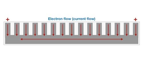
Here is another sliced look at the breadboard. This view shows the positive and negative buses on both sides. A bus in electronics terms is a metal conductor that transfers electric current to components. Each positive and negative connector is a bus that transfers current to each component that touches any point on the bus.
The holes and clips between these two rails work much the same way. The difference is that the clips connect horizontally. The holes in the center are organized in a grid. The columns are labeled from A to J. The rows are numbered from 1 to 30 on this board. This is a small breadboard.
There is a divider running down the middle. This divider is there so we can assemble multiple projects on one board. We can assemble a project using columns A through E and anther using columns F through J. We can bridge this gap using a jumper wire. We will talk about jumper wires once we begin working on the first project.

The best way to learn how a breadboard works is by using it to develop projects.
Basic LED Circuit
The basic LED circuit is my favorite when introducing circuit projects to teachers and students. It provides a good introduction to the basic layout and components in Tinkercad. The circuit is simple and familiar to most people. I used to make flashlights when I was a child.
Basic and advanced components are located in the right panel. Some of the basic components include LEDs, switches, batteries, and resistors. They form the basis of a simple LED light switch. LED stands for Light Emitting Diode. A diode is a component that permits current to flow in only one direction. Current flowing through an LED emits light.
The LED is one of the first components in the list. Click the LED component once. It will attach itself to the mouse pointer.

Move the mouse pointer and LED over the breadboard. The Leads on the LED will want to attach themselves to the holes in the breadboard. Place the LED near the center divider. Don’t worry about placing the LED in the same location like the one shown in my image. There isn’t anything magical about the location where I placed the LED.

Leads on a component are the wires used to connect to other components. Leads in our components will attach to the breadboard rails.
The difference between an LED and a light bulb is important. The differences provide a good opportunity to teach a few concepts. A light bulb uses a filament to generate light. Light is emitted when the filament heats up. It heats up because of current going through the filament. The filament is made of impure metal. This impurity facilitates the flow of electrons and the resistance of electrons at the same time. There is enough resistance to cause heat and light but not so much as to prevent current from flowing through the bulb. It is the resistance that causes the filament to heat up. The heat generated causes the filament to glow. The glow is what provides the visible light we see.
An LED is different from a light bulb because it does not use a filament. It does not rely on resistance to generate light. It uses a semiconductor to facilitate the flow of current. The semiconductor consists of two materials. One is called a P-type semiconductor and the other is an N-type semiconductor. Sorry, we got real technical real fast. It’s okay the purpose is not to understand LED here.
They are assembled inside the plastic container. Electrons flow through the negative side of the LED and excite the electrons on the N-type conductor. The negative conductor. These electrons flow across to the other side with the P-type conductor. The positive conductor. There are holes in the P-type connector where the electrons are forced to flow. The holes are smaller than the electrons. To go through these holes the electrons must lose energy. This energy is given off in the form of photons. Light is composed of photons.
Light bulbs use resistance to generate heat and light. LEDs don’t use resistance. This is why they are cooler than light bulbs and use less energy.
The Resistor
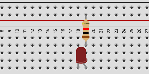
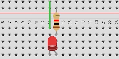
LEDs don’t use lots of energy. They also don’t have much resistance. The typical LEDs we use in a project like this one are sensitive to too much current flowing through them. We need to control the amount of current flowing through an LED. To control the flow of current we need to use a resistor. Select the resistor component and move it onto the breadboard.
The placement of the resistor is important. The LED has two Leads. One of the Leads is bent. This lead is called the Anode. The other Lead is called the Cathode. We send current through the LED into the Anode. This is where we connect the positive battery terminal.
Real physical LEDs don’t have bent leads. The Anode lead on an actual LED is longer than the Cathode.
An LED is a diode and diodes allow the flow of current in only one direction. This direction is from the Anode to the Cathode.
Place the resistor so it lines up with the row that has the Anode on the LED. The other end of the resistor will connect to the positive connector. Current will flow from the positive clips into the resistor. The flow of current is reduced in the resistor and the reduced current flows out the other end. It goes into the clip in the row and into the Anode end of the LED. The current will flow through the LED and exit the LED through the Cathode.

The image below uses arrows to demonstrate the flow of current.

Jumper Wires
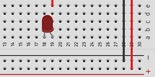
To complete the circuit we need to connect the Cathode end of the resistor to the negative side of our breadboard. To do that we need a jumper wire. A jumper wire is used to bridge connections and gaps in our project. Move your mouse pointer over the row where the Cathode of the LED rests. The hole where our pointer is resting is highlighted with a red square. The other holes are highlighted with green circles.

Click once on the hole in the row with the Cathode and drag the mouse pointer toward the negative terminal rail. A green line follows our mouse pointer. Click once on the negative rail to anchor the other end of the lead wire. Don’t click again anywhere because this will cause another lead wire to be created. Press the ESC key on our keyboard to cancel if this happens.

We have all the elements in place for our basic LED circuit. We need a battery to supply the current.

The battery
Go to the Components panel, find a battery and place it next to the breadboard. There are three battery options available. Most students chose either the 9-volt battery or the Double-A battery. I recommend using the 9-volt battery.

It’s easy to remove components from the work area. Click once on the component and press the delete key on your keyboard. You can also click the trash can icon in the button bar.
Attach a jumper wire from the negative rail on the breadboard to the negative end of the battery terminal.

Repeat the process with the positive end of the battery terminal.
Start the simulator

The circuit is complete. To light the LED we need to start the simulation. Click the Start Simulation button.

The LED will glow in our simulated circuit. Stop the simulation by clicking the Start Simulation button again.
What happens without the resistor?
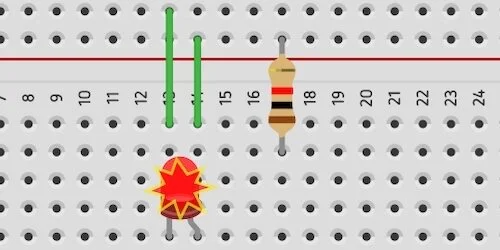
One of the benefits of working with the simulation is that we can make mistakes. Mistakes provide learning opportunities. We used a resistor to limit the flow of current into the LED. Without the resistor, the LED would burn out and possibly blow. I have seen actual LEDs give off smoke from too much current. Click and drag the resistor to the right. Place it a few rows down.
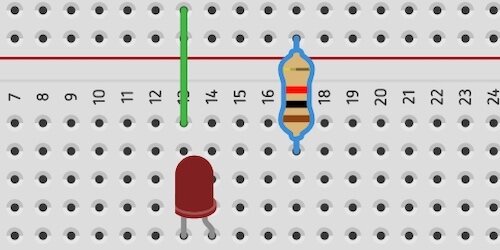
Add a jumper wire from the row with the Anode to the positive rail.

Start the simulation and observe what happens to the LED. The explosion symbol over the LED means that we sent too much current to the LED. A real LED will not work anymore if this happens. Stop the simulation. We’ll add a button so we can use it to turn the LED ON or OFF. That will appear in the next article. In the meantime see if you can attach a button to this circuit on your own.