
Technology lessons for educational technology integration in the classroom. Content for teachers and students.
Change the brightness of an LED with TINKERCAD and Arduino
In this lesson, we explore how Pulse Width Modulation works in a circuit connected to a microcontroller. I am using a virtual circuit constructed in Tinkercad. A microcontroller in Tinkercad, an Arduino, will vary the brightness of an LED. The brightness is adjusted with code entered into the microcontroller. The microcontroller uses Pulse Width Modulation to simulate various levels of illumination on an LED. We will see how pulse width modulation actually works by connecting a virtual oscilloscope to the circuit.

Introduction
In a previous article, I posted a lesson for using TinkerCad to construct a basic LED circuit. The LED in the circuit is turned on or off using an Arduino and a few lines of code. We used code to instruct Arduino when to turn the LED on or off. That’s as far as we got in that lesson. The link to the lesson is below.
https://digitalmaestro.org/articles/electric-circuits-and-arduino-with-tinkercad
In this lesson, I want to take the same instruction one more step. In the previous lesson, the LED was either on or off. We had no way of adjusting the brightness. We are going to address that option in this lesson. The link to the completed project is available below.
https://www.tinkercad.com/things/iOxi8dvvqMP
For this lesson, you need a TinkerCad account. The account is free. Go to tinkercad.com if you don’t have one.
New Circuit
Go over to tinkercad.com and log in. Click the circuits button. The button is in the menu on the left. Click the create new circuit button.

Click the random name assigned to the project. Change the name to variable led brightness.

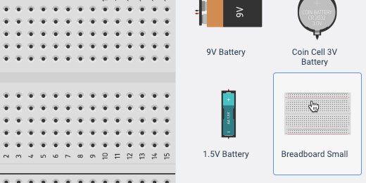
Find the small breadboard in the components panel. Drag it onto the canvas.
Find the LED component.

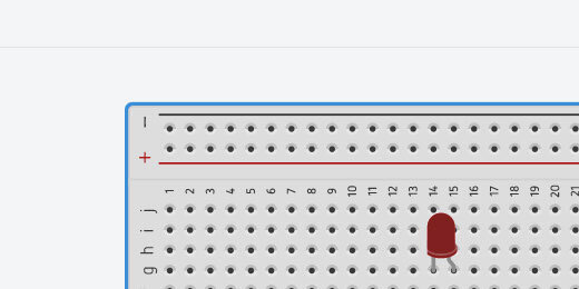
Place the LED on the breadboard. Place it somewhere in the middle. Leave space to attach wires above and below the connectors.

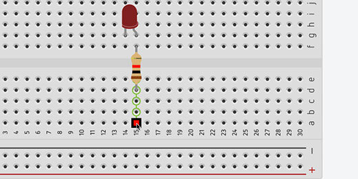
Find the resistor in the components panel.

Place the resistor across the upper and lower halves of the breadboard. Align the resistor with the Anode of the LED. The Anode is represented by the bent connector.

Click on a hole across from the resistor. This activates the wire tool and begins a wire connection.
Click a hole in the positive side of the terminal rails. Press the ESC key on your keyboard to release the wire tool.

Click the wire color selector and choose red.

This connects the resistor and LED to the positive terminal.

Connect a wire from the Cathode on the LED to a negative connection on the terminal. Set the wire color, choose black.

Click somewhere along the edge of the breadboard. This selects the breadboard. We need to reduce the size of the breadboard to make room for the Arduino.
TinkerCAD does not have many menu options. We need to use shortcut keys to manipulate some objects. Use the Alt and the minus(-) key on Windows and Chromebook. Mac users, use the Command and the minus(-) key. Use the Alt or Command key in combination with the plus(+) key to increase the size.

Click and drag the border of the breadboard toward the top of the canvas.
The Arduino is just below the breadboard in the components panel.

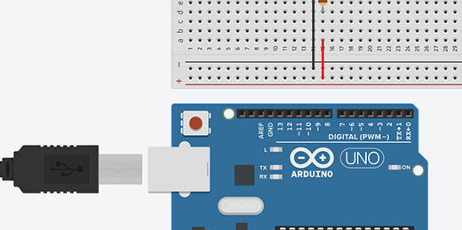
Place the Arduino below the breadboard on the canvas.
Connect a wire from the Arduino GND GPIO to the negative side of the terminal rail. GPIO stands for General Purpose Input/Output.

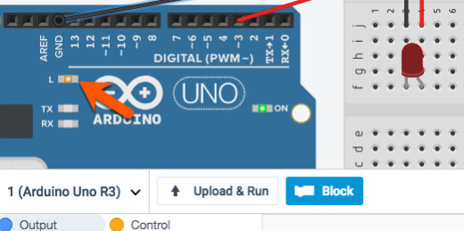
Arduino has several types of GPIO connections. The side of the board we are looking at as numbers from zero to thirteen. GPIO pins 0 and 1 are for transmitting text messages. Pins 2 to 13 are used for components.
Some of the numbers have a squiggly line. This is the Tilde character. Numbers without the tilde represent digital pins. We use these pins to turn the LED On or Off. Digital pins provide On or Off options only. These pins provide either zero volts or 5 volts.
Pins with the tilde character provide Pulse Width Modulation. These pins provide varying voltages.
Connect a wire from pin 6 to the positive terminal.

Coding Arduino
Click the code button to reveal the coding panel.
The panel has some code to get us started. This code is used for the built-in LED.

We don’t need this code. Drag the code blocks to the code section.
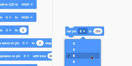
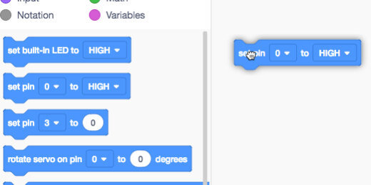
There are two set pin code blocks. One is used with the digital input pins. It has two parameters, high or low. The other set pin code block has a variable parameter. Drag this code block onto the coding area. This is the only code block we need.

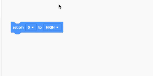
Change the PIN number to 6. Change the variable to 255.
Click the Start Simulation button.

The LED should be on.

Click the Stop Simulation button.

Change the variable to 128. Start the simulation.

The available numbers for the variable range from 0 to 255. The total is 256. The value of 128 represents half of 256. The LED will light with half the illumination.
It is hard to tell but the LED is shining with half the brightness.

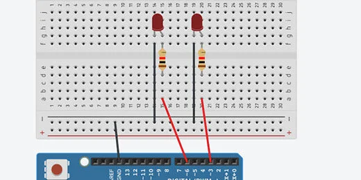
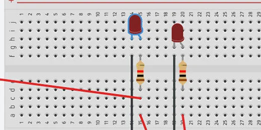
Let’s add another LED to help us with the comparison. Add another LED to the right of the current LED. Add a resistor and make all the same connections. There is one change we need to make. Don’t connect the resistor to the terminal rail.
Each LED needs to be controlled by a separate PIN. Connect the wire from the resistor directly to the GPIO pins on the Arduino. The original LED remains connected to PIN 6. Connect the other LED to PIN 3.
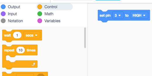
Open the code panel. Add another set pin code block. Place it after the existing code block. Set the pin to 3. Set the value to 255. Start the simulator.

That doesn’t help too much. There is a slight difference.

Stop the simulator. Change the variable for the first LED to 64. Start the simulator.

The difference is a little easier to see.

Pulse Width Modulation
What is pulse width modulation? It turns out that pulse width modulation is a sneaky way to simulate a lower voltage. This is easier to understand by using an oscilloscope. Oscilloscopes display the change in electronic signals over time. The oscilloscope will show us the voltage going through the circuit.
Click the Code button to close the code panel.

Click in the components search box. Type oscilloscope. Select the oscilloscope.

Place the oscilloscope on the left side of the breadboard. Adjust the size of the components so the oscilloscope is visible.

The oscilloscope has connectors. Click the connector on the right to create a wire.

Connect the wire to the resistor before it connects to the LED.
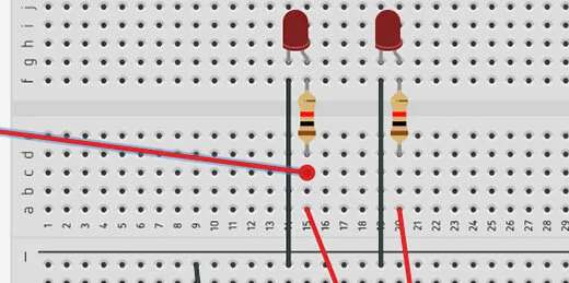
Move the LED up to make room for the next wire.
Connect the wire from the negative terminal of the oscilloscope to the cathode of the LED.

Click on the oscilloscope to select it.

Go to the oscilloscope configuration box. Change the measurement from ms(milliseconds) to (us)microseconds.

Change the time per division to 500. These parameters will display the frequencies from the voltage in 500-microsecond increments.

What is a microsecond? Think of a second. That is fast. A second is divisible into smaller time units. The next level of time is in milliseconds. There are one thousand milliseconds in one second. A microsecond is a millionth of a second. One million microseconds make one second. That is very fast.
Electricity travels very fast. Choosing microseconds slows things down so we can see the patterns on the oscilloscope.
Open the code editor. Change the variable to 255.

Start the simulator and look at the oscilloscope. A blue line appears on the oscilloscope. This line represents 4.85 volts.
Stop the simulator. Change the variable to 0. Start the simulator. The blue line is in the middle. This represents no voltage going to the LED.

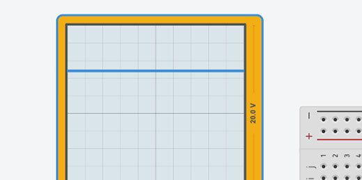
Stop the simulation. Change the parameter to 128. Start the simulator again. The simulator shows lines going up and down.

Let’s take a closer look. When a line appears at the top we know it represents 5-volts. A line at the center represents 0-volts.
This line isn’t flat. The line is at 4.85-volts for a time and then at 0-volts for another time.

The screen has a grid. The vertical lines represent 5ms. The gap between each line is 5ms long.

The oscilloscope shows that the voltage is zero for 5ms and then it is 4.85-volts for another 5ms. This pattern repeats.

Let’s think about what is going on. The voltage changes from 0 to 4.85 very quickly. This is like flipping a light switch on and off very fast. The LED is fully light for 5ms then off for 5ms. It is on half the time. The value we placed in the parameter is 128. This represents half the available voltage going to the LED.
Arduino is flipping the voltage on and off to simulate half the voltage going to the LED.
Stop the simulation. Change the parameter to 64. Start the simulation again. The bars in the simulation at the top are shorter than those at the bottom.

A short bar at the top represents a short time where the voltage is 4.85-volts. A longer bar at the bottom represents the voltage at 0-volts.
How long do you think the voltage is set to zero? The space between the vertical lines is 5ms. The line extends about halfway into the next space. This is roughly 7.5ms. The LED is off for 7.5ms and on for 2.5ms.
The parameter of 64 represents one-quarter of the total voltage. Think of it this way. A value of 128 is half of 256. A value of 64 is half of 128 and a quarter of 256. The LED is on for one-quarter of the time and off for the remainder, three-quarters.
The LED is on for less time and this causes the LED to look dim.
Our human eyes don’t see this pulsing. The pulses are so fast that our eyes take an average of what is going on. We don’t see a blinking LED but a dim LED. This is why we need an oscilloscope. To slow things down.
The voltage is pulsing through the LED. Probably where the name Pulse Width Modulation came from.
Electric circuits and Arduino with TinkerCAD
In the lesson, we create a basic circuit in TinkerCAD. We create a basic LED circuit. We combine the basic circuit with an Arduino microcontroller. We use the microcontroller to turn the LED ON and OFF. We take it one step further and program the LED to blink. A good lesson to learn the fundamentals.

Coding Circuits With Arduino in Tinkercad
An Arduino is a microcontroller. A microcontroller is a very simple computer that accepts basic code. It translates that code into instructions that interact with the physical world. In this lesson, we will use a microcontroller to act as a switch.
Click the link below to see the completed project.
https://www.tinkercad.com/things/3sufhjgf15T
Create a new circuit in TinkerCAD. Add a Breadboard to the work area. Place one LED on the Breadboard and place two jump wires. Connect one jumper wire to the positive rail. Connect the other to the negative rail. Make sure to connect the anode to the positive lead and the cathode to the negative lead. The Anode on the LED is the the one with the bent wire.
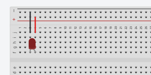
LED on breadboard
Click on the Components button and find the Arduino Uno R3 microcontroller.

Arduino Uno R3 component
Place the microcontroller to the left of the Breadboard. Several components are part of the Arduino board. Let’s look at a couple of these components.
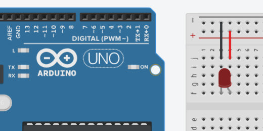
Arduino alongside the breadboard and led circuit.
The holes along both sides of the board are GPIO pins. This stands for General Purpose Input/Output pins. Each is a connector that links to our Breadboard with a jumper wire. Most of these are with a number. These numbers identify the pins in our code. The code we develop on the board can reference these pins as either input or output. There is one connector labeled GND. This is the ground connector or the negative terminal in our circuit. The Arduino provides coded instructions to the components on the board. It also provides the necessary current to make the components work. The GND is the same as the negative terminal on a battery. The other connectors marked with a number are the same as the positive terminal on a battery.
A physical Arduino board connects to a five-volt power supply from a computer USB port. The Arduino itself supplies the same 5 volts to components. For some components, this is too many volts. In our example, the 5 volts will destroy the LED on the Breadboard. We will be adding a resistor to limit the amount of current going to the LED.

GPIO PINs on Arduino
Connect a jumper wire from the GND connector on the Arduino to the negative rail on the breadboard. Take another jumper wire and connect it from the number 3 GPIO to the positive column. I moved the board so you could see the connections. I also color-coded the wires.

Jumper wires from breadboard to Arduino.
This isn’t enough to turn on the LED. We need to do a few more things. Click on the Code Editor button.

Code editor button
A coding panel will open at the bottom of the page. We use blocks to develop code. Like the blocks used in Code.org or Scratch. There is already a program in the editor. This is the standard code included each time we place an Arduino board onto the workspace. This code instructs the LED on the Arduino board to blink. This is not the LED on our Breadboard. The Arduino has a small LED on the board. Click the Start Simulation button to see the LED on the board blink.

LED code block for Arduino.
The blinking LED is on the left side of the Arduino logo. Stop the simulation.
Blinking LED on Arduino board.
We don’t need this code. We want to control the LED on the Breadboard. Click on the first code block and drag it to the trash can icon. This takes everything that is connected to it.

Removing the standard LED code.
We need a little more room to code. Move your mouse pointer to the top edge of the coding panel until you see the arrow change. Click and drag up to expand the coding panel.

Widen the code area.
The coding panel has different sections of code. We will be using code blocks in the Output section. Drag the set pin code onto the coding canvas.
Set pin code block onto canvas.
Most code blocks have options. This code block includes a PIN and a state. The PIN references the connector we used to send current to on the Breadboard. This is the positive jumper wire we connected earlier. We connected the wire to pin 3. The options in the code block are arguments.
The term argument comes from mathematics. The argument of a function is a specific input to the function. It is an independent variable like the pin in our code block. This code block has two arguments.
Set pin code and parameters.
Change the pin to 3. The second argument has two states. A state has one of two options. A state can be on or off. The state is set to high. A high state is the same as ON. The other option is a LOW state. This is the same as OFF. Computers read everything as either ON or OFF.
That’s all we need to get started. Click the Start Simulation button. Resize the code block panel to see the LED.

Parameter set to pin 3.
The LED will change color to show that it is on. There is an exclamation mark next to the LED. This exclamation mark is a warning. The current going through the LED is too high. In the simulation, we get a warning. In a physical board with a real LED the LED would burn out and won’t work again. This is why testing or prototyping is useful. LEDs aren’t expensive but expensive enough that you don’t want to be burning them out all the time.
To avoid burning out LEDs we need to use resistors. Resistors restrict the flow of current to components. Every circuit includes voltage, resistance, and current. Current is the part of the equation that does all the work. Think of electric Current like water flowing through a river or stream. Resistance is the width of the river or stream. Narrow streams have more resistance than wide streams.

LED light with warning.
Stop the simulation and close the code editor. We need to make room for the resistor. Move the LED to the other side of the board. Place it in column A.

Changed position of LED on breadboard.
Open the components panel and find the resistor.

Resistor in component panel.
Place the resistor so it bridges the gap between the two halves of the board. Make sure the resistor is in the same row as the anode and the positive jumper wire.

Resistor on breadboard.
The row connections do not span across the board between E and F. Add a jumper wire to complete the circuit.

Jumper wire to complete circuit.
Run the simulation and the LED should light.
Blinking LED
The code we used in the previous example turned the Arduino into a glorified switch. We can do so much more with Arduino.
Click the code editor button to open the coding panel. Click the Control code block category and look for the wait code block.
Wait code block.
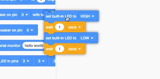
Place the wait code block below the set pin code block. The wait argument is set to one second. Leave the argument at this value. Go back to the Output code block category. Place another set pin code block onto the canvas below the wait code block.

Second set pin code below wait block.
Set the pin value to 3 and the state to low. Run the simulation. The LED will turn ON and OFF. The OFF state is too short. Arduino is a very simple computer but it is still very fast. It processes our instructions in fractions of a second. We need to instruct the code to slow things down so we have time to see the changes.

Set pin block with updated parameters
Go to the scripts panel and find a wait code block. Add a wait code block after the last pin code blocks. Leave the wait value at one. Run the simulation again. The LED will turn on and off over and over again. The code we write does not include a loop function but the Arduino repeats the code anyway.

Second wait code block
The code blocks we use are representations of written code. The written code is on the right side. The code has two main sections or functions. The void setup function sets pin 3 as the output pin for the instructions.
The void loop function is where we write the main part of our code. The void loop repeats the code until the simulation stops. On a physical Arduino, we need to turn the power OFF.

The script represented from the code blocks
The void loop instructs the board to set the power to pin 3 to high or On then wait one second. After one second the power to pin 3 is set to low or turned off and then wait one second. The instructions repeat all over again until we stop it by removing power from the Arduino board.