Tinkercad Transistor circuits

Transistors
Transistors and LEDs have revolutionized our modern world. Transistors have made fast and small computers possible. In this lesson, we will learn to use the transistor as a switch.
Transistors have three leads. Each lead has a name and a purpose. The center lead is called the Base. The leads on either side are called the Collector and Emitter. You will see an image of this transistor later in the lesson. The location of the emitter and collector depend on the type of transistor being used. There are two types of transistors. Each transistor is referred to as either a PNP or NPN transistor.
The difference in the type of transistor depends on how it is manufactured. The NPN transistor is the most popular and common. Each end of the transistor is made of a semiconductor material that is saturated with electrons. The center material is depleted of electrons. This positively charged layer is sandwiched between two negatively charged layers. This is the transistor we will use in our lesson.
The PNP transistor is not as common. This transistor has a negatively charged layer sandwiched between two positively charged semiconductors.
For the transistor to work as a switch the base must receive electric current. The current stimulates the base to allow the flow of current across the collector and emitter. We typically have two power sources for a circuit with transistors. One power source activates the base and another source powers a component. Our first project will have one power source. The first project will help us compare how the second project with two power sources differs and the advantages of having two power sources.
Switches
For this project, we will need a breadboard, LED, resistors, button, and transistor. Create a new project. Place a small breadboard onto the work area. The first step is familiar. Attach a resistor to the board. One end connects to the positive rail. Add the LED so the Anode is on the same connection as the resistor. The current must flow into the LED through the Anode lead.
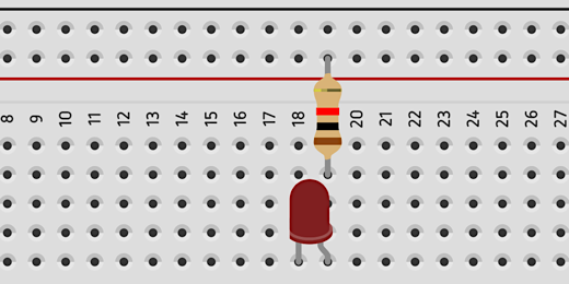
This circuit is going to have a few more components than our other circuits. I want to have plenty of room to keep things easy to see. Move the LED to the other half of the breadboard. Place it on the bottom of the board.

Use a jumper wire to connect the resistor to the Anode on the LED.

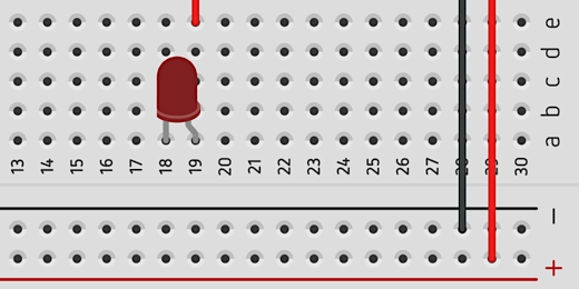
Get a 9-volt battery and attach jumper wires to the top half of the board.

We are using the lower half of the board too. Run jumper wires from each rail in the top half of the board to the lower half.
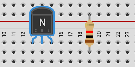
In the LED circuit, we placed a push-button between the Cathode and the negative rail. We are going to do the same thing here but we will use a transistor as our button to close the circuit. Find an NPN transistor in the components panel. It’s in the basic set of components.

Place the transistor in the top half of the board next to the resistor. A transistor has three parts. It has a collector, base, and emitter. The transistor on our board has the letters C, B, and E to help identify the parts.
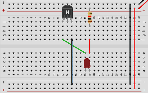
Connect a jumper wire from the Cathode on the LED to the Collector on the transistor. The Collector is labeled with the letter C.

Circuits run in loops. To complete the loop in this circuit we need to connect a jumper wire from the emitter to the negative rail. The transistor is large like the capacitor in our previous lesson. Instead of moving the transistor to attach a jumper wire we will attach it to the bottom of the board.
We don’t have a complete connection yet. Press the Start Simulation button. The LED doesn’t light because we don’t have a closed circuit. We need to pass current into the base of the LED to close the circuit.
Let’s take a moment to see how this circuit resembles a previous circuit. If we replace the transistor with a switch it looks like one in a previous lesson.
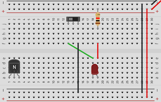
This is the part that makes it all work. Connect a resistor to the base of the transistor. The resistor will connect with the lower half of the board. Connect a jumper wire from the other end of the resistor to the positive rail. The current running from the positive rail through the resistor and base of the transistor is what activates the transistor.

Press the Play Simulator button. The LED will light.

The current flowing into the base of the transistor is what causes the transistor to close the circuit.
At this point we have a discussion noting the similarities and differences between a transistor, push-button, and switch. We discuss how the transistor is like a push-button and how it is like a switch.
Students have discussions in small groups. They discuss when a transistor as a switch would serve better over a regular switch. What are the advantages and disadvantages of using a transistor as a switch in a simple circuit?
Title the circuit Basic Transistor circuit and click the Tinkercad icon to return to the Tinkercad Circuits page.
This basic transistor circuit uses one power source to activate the transistor and light the LED. Let’s take a look at a circuit where we use a smaller current to pass a larger current to a circuit.
Amplification
The circuit for this lesson is similar to the one in the previous lesson. We don’t need to recreate the whole project. We will be using many of the same components.
We’ll make a copy of the previous circuit and use it for the next. Hover your mouse over the circuit preview of the previous project. Click the gear icon that appears in the upper right corner.

Select the Duplicate option.

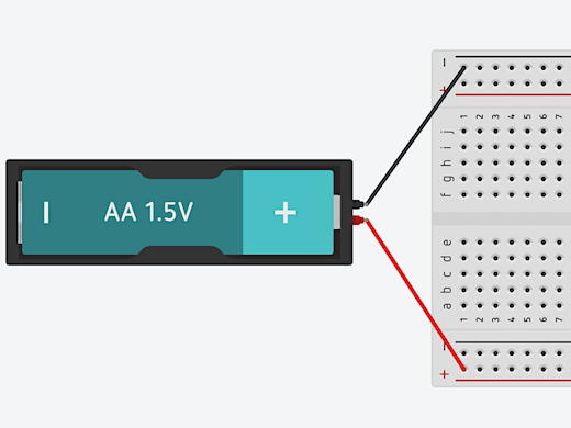
A copy of the circuit will be created and opened. The first thing we are going to do is replace the 9-volt battery with a AA battery. Click once on the 9-volt battery and press the delete key on your keyboard. Find a 1.5 volt AA battery and place it next to the board.
The terminals on the battery are at a right angle to those on the breadboard. I like to rotate the battery so the terminals are parallel.

There is a rotate button in the button bar next to the trashcan icon. Clicking the button will rotate a component clockwise. Make sure the AA battery is selected and click the rotate button once or twice. We need to do a lot of clicking to rotate the battery in this direction. Hold the Shifty key on your keyboard when clicking the rotate button to rotate counter-clockwise.
Connect the terminals to the board with jumper wires. The terminals don’t align so the wires will cross. This is where color-coding helps.

We reduced the voltage of the battery. In doing so we reduced the amount of current going to the circuit. Press the Start Simulation button to see the result on the LED. The light from the LED is fainter.

Stop the simulation and get another 1.5 volt AA battery. Place this battery on the opposite side of the board. Rotate the battery. Connect one jumper wire to the negative rail at the top of the board. Connect another jumper wire to the positive rail at the bottom of the board. This battery will serve as the source for the Base of the transistor. It will trigger the switch to allow current to flow through the transistor and circuit.
This battery provides the power source for the transistor base. We don’t need the power from the other battery yet. Remove the jumper wire connecting the battery on the right side of the board. Leave the wire for the negative connection. We still need a ground connection for the emitter.

We want the LED to shine brighter so we need more current. To get more current we need more potential energy in the form of volts. Click once on the 1.5 volt AA battery on the right side of the board. The configuration panel for the battery shows a count of one battery.
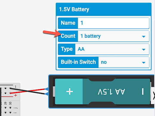
Click the battery count selector and choose 4 batteries.

Click the Start Simulation button. The LED is much brighter now.

Click once on the battery on the left side. Go to the configuration panel for the battery. Change the built-in switch option from No to Yes.

The battery will be enclosed in a case with an ON/OFF switch. Click once on the switch to turn the battery current OFF. This battery supplies current to the transistor. When current from this battery stops, the current to the transistor stops. This opens the circuit and prevents the current from batteries on the other side. No current means our LED won’t shine.
