Buttons and switches in Tinkercad circuit projects

Buttons in an LED circuit
A switch or button is used to close a circuit. Current in a circuit flows from the positive side of a power source to the negative side. A closed-circuit is required to enable the flow of electrons from the positive side of the battery terminal to the negative side.
We’re going to build on the same circuit from the previous article, A Basic LED Circuit with Tinkercad.
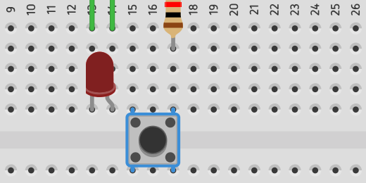
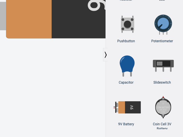
Go to the Components panel and look for the push button. It has a circle in the center of a square. Place the push button on the right of the LED. We will use the button to bridge the center division of the breadboard. Half of the button should be on one side and the other half on the other.
We need to move our components around the board to complete the circuit. Move the LED so the Anode lead is on the same row as the lead for the left side of the switch.
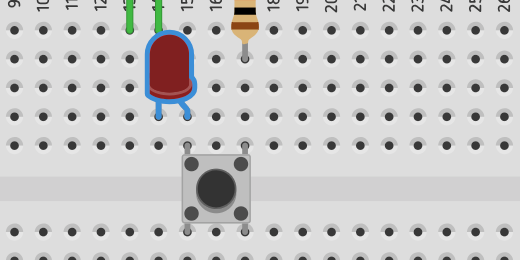
Move the resistor to the other side of the board. Align the resistor to the right lead of the push button. One end of the resistor needs to connect to the positive rail on the board.

We need to reposition the two jumper wires. The jumper wire that connects to the LED Cathode lead needs to connect to the negative rail.

Click once on the jumper wire. Circle handles appear at each end of the wire. Use the handle on the positive rail to move the end of the wire to the negative rail.
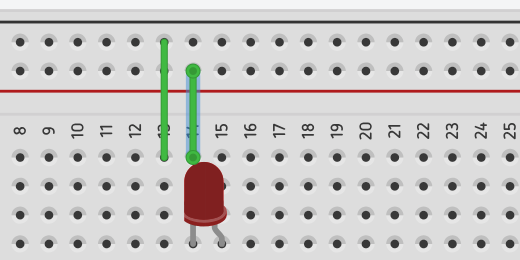
Click once on the jumper wire to the left of the one we positioned. Click and drag the top of the wire to the right.

Place the wire near the jumper wires for the battery. Connect it to the positive side of the rail.

Move the other end of the wire to the other side of the board and connect it to the positive rail too. This is how we distribute current to both sides of the board when using one battery.

jumper wire across breadboard
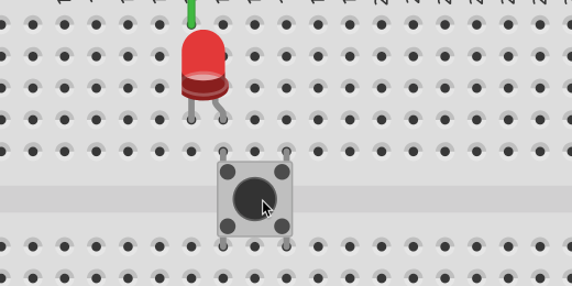
Let’s take a closer look at the push-button connection. Think of the button like a road with two lanes. Current flowing in each lane will flow uninterrupted. The current flowing through the right lead is not prevented from flowing through the button. The current cannot go to the other lead, the one on the left, unless the button is pressed. Pushing the button closes the circuit and current flows from the right lead to the left lead. Like a car changing lanes.

Press the Start Simulation button. Press the push button with your mouse to light the LED. Keep the button pressed on your mouse to keep the LED light. Release the button to turn OFF the LED. The LED remains light as long as we keep pressing the button.
Using A Switch
A switch is an option to light the LED without keeping our finger or the arrow on the push button. We’ll replace the push button with a switch. Click once on the push button and press the delete key on your keyboard. If the button isn’t removed, make sure the simulator is stopped. Go to the Components panel and find the switch.
Place the switch on the board. Place the center lead of the switch in the same row as the resistor. Place it in the column above the resistor.
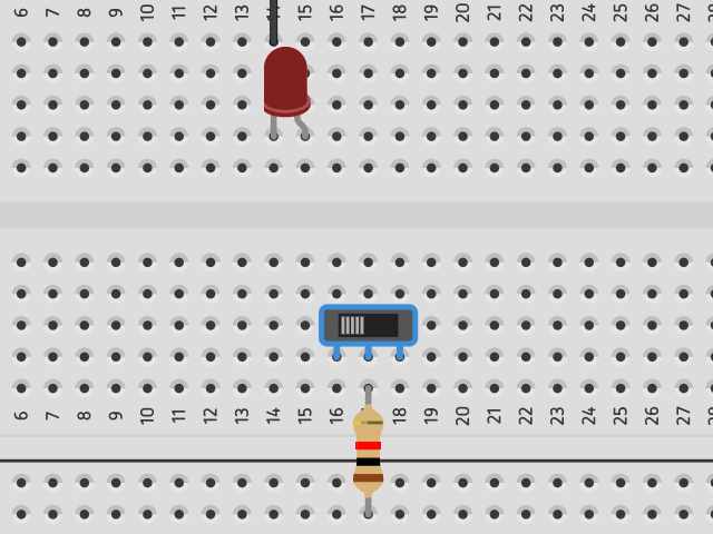
The center lead on the switch is called the Common. This is where the current flows into the switch.

The leads on either side of the switch are called terminals. The lead on the left is called Terminal 1. The one on the right is called Terminal 2.

Connect a jumper cable from Terminal 1 to the Anode on the LED.

There is a slider on the switch. The slider is currently connecting the Main to Terminal 1. This is creating a closed circuit. Click the Start Simulation button. The circuit is closed and the LED will light.

Slide the switch to the right to turn the LED OFF.